
Outback Radian AC Coupling Note


Application Note
©2019OutBackPower,Arlington,WA98223FB‐MM‐2/22/2019Page11of12
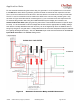
If the automated method of disabling the GTI during generator operation cannot be approved by the local
authorities having jurisdiction, then there is a manual method where the generator is connected to the
G
EN IN AC input terminals in the GSLC load center. The Generator input mode should be selected for
the Gen AC Input Mode and Limits under the Inverter settings.
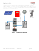
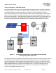
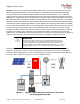
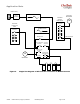
Figure 8 shows a single line diagram with the generator connected. The manual operation whereby the
GTI is disconnected with the 30A CB/Disconnect BEFORE manually starting the generator will ensure
that the generator does not get back-fed by the GTI when it is producing power from the PV array.
CAUTION: Equipment Damage
The GTI disconnect must always be open when manually operating the generator
or the generator could experience catastrophic failure if power is back-fed from
the GTI.
Where the previously discussed automated solution using the 2PDT GTI disconnect relay is not allowed,
this could provide a way to charge the battery bank and power loads when the GTI is not able to sustain
the load and battery charging demands. Please note the CAUTION above.
120V/240V
GRID FEED
120V/240V
200 Amp
Main Service
M
200A
Disconnect
120V/240V
Critical Load
Panel
AC In Bus
50A DPST
DC Disconnect
175A SPST (2x)
AC In BUS Gen
50A DPST
GSLC Load Center
AC Out BUS Grid
50A DPST
DC Neg
GS8048 Inverter
6kW PV Array
6kW Grid Tie Inverter
12V
12V
12V12V
200A
Disconnect
50A 120V/240V
30A DPST
String
Combiner
G
GTI Disconnect
Generator
Figure 9 Single line diagram of manual generator start
and GTI disconnect method