
Installation Guide

Installation
900-0144-01-01 Rev B
37
The three outputs operate independently of each other. Each can run in independent Search mode if
desired. This does not normally occur when three-phase loads are connected.
The output of each inverter is 120° out of phase from the others. Any two outputs produce 400 Vac
between them. The outputs can be used to power three-phase loads when all inverters work together.
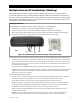
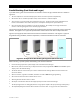
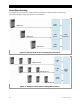
Up to nine inverters, three per phase, may be installed in a three-phase arrangement. Figure 32 shows three
inverters, as do the figures on the following pages. Figure 33 shows nine inverters.
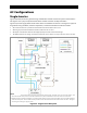
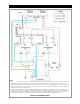
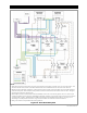
Figure 34 (see page 38) shows the general wiring of the Radian inverters and the AC system connected
to them. This figure is not a physical representation of the inverters and does not depict the GSLC.
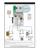
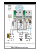
Figure 35 (see page 39) shows the locations of AC and network connections. This figure is a physical
diagram for wiring the GSLC, network components, and external AC devices with each inverter.
When installing a three-phase system, the following rules must be observed.
Three-phase stacking requires the system display and an OutBack communications manager.
~ Three-phase stacking with only three inverters can be performed with any HUB product.
~ Three-phase stacking with more than three inverters requires a HUB10.3 Communications Manager.
One inverter, and one inverter only, is always the master and is programmed as
Master
in the MATE3 system
display. This is the default setting.
The master inverter must be connected to port 1 of the communications manager. Other inverters must not
be selected as master.
Two subphase master inverters are required regardless of whether any slave inverters are installed. One
subphase master controls the phase B output. The other controls phase C. The inverters should be wired to
the loads and to the AC sources in phase order.
If a HUB4 or HUB10 is used, the B and C subphase master inverters can be connected to any port other than
port 1.
If a HUB10.3 is used, connect the inverters using the following rules.
~ Any phase A slaves must be connected to either port 2 or port 3. They are programmed as Slave.
~ The subphase master for phase B must be connected to port 4. It is programmed as B Phase Master.
~ Any phase B slaves must be connected to either port 5 or port 6. They are programmed as Slave.
~ The subphase master for phase C must be connected to port 7
. It is programmed as C Phase Master.
~ Any phase C slaves must be connected to either port 8 or port 9. They are programmed as Slave.
All overcurrent devices must be sized for 50 Aac or less. All wiring must be sized for 50 Aac or more.
All output circuit breakers must be sized appropriately for loads and inverter wattage.
The AC input (generator or utility grid) must be 230/400 Vac at 50 Hz (a three-phase wye configuration).
The input/output bypass kit for the GS Load Center cannot be used. See page 10 for more information.
IMPORTANT:
The HUB4 and HUB10 literature states that it is necessary to move the jumper to
the “three-phase” position. That statement does not apply to the Radian
inverters. The jumper must be left in its original position.
In the HUB10.3, the jumper must be moved to the position required by the
HUB10.3 literature.