Radian Series Inverter/Charger GS4048A GS8048A Installation Manual
About OutBack Power Technologies OutBack Power Technologies is a leader in advanced energy conversion technology. OutBack products include true sine wave inverter/chargers, maximum power point tracking charge controllers, and system communication components, as well as circuit breakers, batteries, accessories, and assembled systems. Applicability These instructions apply to OutBack inverter/charger models GS8048A and GS4048A only. Contact Information Address: Corporate Headquarters 17825 – 59th Avenue N.
Table of Contents Introduction ..................................................................................... 5 Audience ......................................................................................................................................... 5 Symbols Used ................................................................................................................................. 5 General Safety ....................................................................................
Table of Contents List of Tables Table 1 Table 2 Table 3 Table 4 Table 5 Table 6 Components and Accessories ............................................................................................ 7 Battery Bank Elements...................................................................................................... 12 Ground Conductor Size and Torque Requirements .......................................................... 25 DC Conductor Size and Torque Requirements ..............................
Introduction Audience This book provides instructions for the physical installation and wiring of this product. These instructions are for use by qualified personnel who meet all local and governmental code requirements for licensing and training for the installation of electrical power systems with AC and DC voltage up to 600 volts. This product is only serviceable by qualified personnel.
Introduction Welcome to OutBack Power Technologies Thank you for purchasing the OutBack Radian Series Inverter/Charger. This product offers a complete power conversion system between batteries and AC power. It can provide backup power, sell power back to the utility grid, or provide complete stand-alone off-grid service.
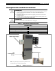
Introduction Components and Accessories IMPORTANT: The Radian inverter is compatible with the MATE3 class of system display products. It can be used with any firmware revision of MATE3s. It can only be used with MATE3 revision 002.017.000 or higher. The MATE3s system display must be used when upgrading the inverter to firmware revision 001.006.063 or higher. The Radian inverter is not intended for use with the OutBack MATE or MATE2 products.
Introduction NOTES: 8 900-0160-01-01 Rev B
Planning Applications OutBack inverter/chargers are designed to use a battery bank to store energy. They work together with power from the utility grid or from renewable energy sources, such as photovoltaic (PV) modules, wind turbines, and other renewable sources. These sources charge the battery, which is used by the inverter. The Radian inverter has two sets of AC input terminals. Two AC sources, such as a gas or diesel generator and the utility grid, can be connected.
Planning Input Modes The Radian inverter has many modes of operation. See the Radian Series Inverter/Charger Operator’s Manual for additional information on these modes, including reasons and considerations for using each mode. The modes determine how the inverter interacts with an AC source. Each mode has functions and priorities that are intended for a designated application. Each of the Radian’s two AC inputs can be set to a different operating mode to support different applications.
Planning Renewable Energy The Radian inverter cannot connect directly to PV, wind turbines, or other unregulated DC sources. The batteries are the inverter’s primary source of power. A renewable energy source is always treated as a battery charger, even if all of its power is used immediately by the inverter. The renewable source must have a charge controller, or some other regulation method, to prevent overcharging.
Planning Bank Size: Battery bank capacity is measured in amp-hours. Determine the required bank specifications as accurately as possible, beginning with the items below. This avoids underperformance or wasted capacity. These ten items are obtainable in different places, summarized in Table 2. Some of the information is specific to the site or application. Some can be obtained from the battery manufacturer. Information on OutBack products is available from OutBack Power Technologies or its dealers. A.
Planning To Calculate Minimum Battery Bank Size (refer to previous page for letter designations): 1. The load size, item A, is measured in watts. Compensate this figure for efficiency loss. Multiply the conductor efficiency by the inverter efficiency (E x F). (These items are represented as percentages, but may be displayed as decimals for calculation.) Divide item A by the result. 2. Convert the compensated load into amperes (Adc). Divide the step 1 result by the system voltage (G). 3.
Planning Generator These Radian models can work with any “split-phase” generator that delivers reliable AC power at the appropriate system voltage and frequency. They cannot work with a single-phase or three-phase generator. CAUTION: Equipment Damage Use of a three-phase generator with this equipment may damage either the inverter or the generator. This damage to the inverter is not covered by the product warranty. The inverter/charger can provide a start signal to control an automatic start generator.
Planning Inoperative Radian Inverter AC Loads GSLC Bypass AC Source Input Wiring Output Wiring Figure 4 Bypass Switching Both manual and automatic double-throw bypass switches are commonly available in a range of sizes and options. These are highly recommended for systems with more than a single inverter. WARNING: Shock Hazard or Equipment Damage Using independent bypass devices on multiple inverters can result in power being routed to inappropriate places.
Planning NOTES: 16 900-0160-01-01 Rev B
Installation Location and Environmental Requirements Radian series inverter/chargers must be located indoors or in a weather-proof enclosure. They are not designed for exposure to water, salt air, or excessive wind-blown dust and debris. The Radian inverter must be wall-mounted in an upright position. The inverter is not approved for mounting in any other position or orientation. These inverters will perform more efficiently in locations offering plenty of air circulation.
Installation 0.45” (1.1 cm) Width 16.0” (40.6 cm) 0.45” (1.1 cm) 8.75” (22.2 cm) 13.7” (34.8 cm) 28” (71.1 cm) 29.0” (73.7 cm) 45.0” (114.3 cm) 12.5” (31.8 cm) This illustration can be used as a basic template for planning layouts, marking mounting holes, etc. when installing a system. The requirements for mounting the Radian inverter are described beginning on the next page. 14.0” (35.
Installation Tools Required The following tools may be required for this installation: Wrench and socket sets; should include ~ torque and ratchet wrenches Insulated screwdriver set (flat and Phillips; should include ~ reversible (stubby) wrenches for narrow access ~ ~ offset box wrench, ½” or 13 mm Wire cutters/strippers #2 Phillips screwdriver 15 to16” long Long-nose pliers High-resolution voltmeter Mounting Two or more people may be needed to install the Radian inverter/ch
Installation …continued from the previous page… 2. Radian Place the Radian inverter against the wall and slide it directly over the upper lip of the mounting plate. The inverter’s mounting flange should come to rest within the lip so that it hangs securely. To assist in alignment, dimples have been placed on the side of the unit to mark the lower edge of the flange. In the picture to the left, the two x symbols show the location of the dimples. xx Mounting 3.
Installation Component Mounting The top of the GS Load Center (GSLC) connects to the bottom of the Radian inverter using four keyhole slots. The keyhole slots fit over four screws on the bottom of the inverter that secure the GSLC to the inverter when tightened. (The long screwdriver recommended on page 19 may be needed to reach these screws.) The GSLC should be secured to the wall using screws or wall anchors.
Installation Removing Front Cover The front cover must be removed in order to access the Radian inverter’s AC terminals and other connections. These include the REMOTE and BATT TEMP ports, as well as several sets of auxiliary terminals. Twenty-two machine screws are located around the perimeter. Remove these screws with a #2 Phillips screwdriver. Once they are removed, the cover can be lifted off. NOTE: The screws which secure the plastic plates to the cover do not need to be removed.
Installation Terminals and Ports DC TERMINALS Connects to the battery cables and DC system. There are two DC positive and two DC negative terminals. Each DC positive terminal requires separate cables and separate overcurrent protection. See page 26 for instructions. RIBBON CABLES Connects the Radian’s power modules and control board. See Warning below. ON/OFF INV JUMPER (J3): Overrides the SWITCH INV terminals when installed. When installed, the inverter is On.
Installation CONTROL WIRING TERMINAL BLOCK: Receives control wires for a variety of functions, including generator control. REMOTE and BATTERY TEMP PORTS: Receive the RJ45 and RJ11 plugs from the MATE3 system display and Remote Temp Sensor. See page 32 for instructions. AC TERMINAL BLOCK Receives AC input wires for two input sources (L1, L2, and N for each). Also receives AC output wires (L1, L2, and N). All neutral wires are electrically common. See page 29 for instructions.
Installation Wiring It will be necessary to remove knockouts from the chassis to run wires. Bushings are included with the hardware kit to protect the wires. Make sure to install these bushings in the holes. Use copper wire only. Wire must be rated at 75°C or higher. Grounding WARNING: Shock Hazard This unit meets the IEC requirements of Protection Class I. The input and output circuits are isolated from ground. The installer is responsible for system grounding according to all applicable codes.
Installation DC Wiring WARNING: Shock Hazard Use caution when working in the vicinity of the inverter’s battery terminals. CAUTION: Equipment Damage Never reverse the polarity of the battery cables. Always ensure correct polarity. CAUTION: Fire Hazard The installer is responsible for providing overcurrent protection. Install a circuit breaker or overcurrent device on each DC positive (+) conductor to protect the DC system.
Installation The Radian inverter has four battery cable terminals, two positive and two negative. Each terminal is a threaded hole which accepts a hex bolt (provided). Notes on assembly and cabling are shown on the next page. GS8048A Figure 15 GS4048A GS8048A and GS4048A Battery Terminals Table 4 DC Conductor Size and Torque Requirements Nominal DC Amps Conductor Size (Minimum, per breaker) (Derated 125%) (Minimum, per breaker) GS8048A 104 2/0 AWG (0.
Installation If the battery cables are connected directly to the Radian inverter, the hardware should be arranged as shown in image A. The inverter’s battery terminal is a threaded hole which accepts a hex bolt (provided). The battery cable lug must have a 0.79 cm (5/16") diameter hole. If the inverter is installed with the GS Load Center (GSLC), follow GSLC instructions for hardware installation. The hardware should be arranged according to the appropriate image below.
Installation AC Wiring WARNING: Shock Hazard The neutral and ground conductors should be mechanically bonded. Ensure there is no more than one AC neutral-ground bond at any time. Local or national codes may require the bond to be made at the main panel only. The GS Load Center (GSLC) is equipped with its own bond, which may need to be removed. CAUTION: Equipment Damage The Radian inverter cannot be connected to a three-phase source (utility grid or generator).
Installation The L1 and L2 GEN terminals are used to connect to the “hot” wires on a 120/240 Vac generator. Three neutral (N) terminals are available. These terminals are electrically common. Any of them can be used to connect to neutral wires from various parts of the system. The most common connections are to the neutral bus on the main panel or utility grid service, the neutral bus on the output load panel, the neutral bus in the GSLC, and the neutral wire from a generator.
Installation AC Sources The inverter’s transfer relay is normally set to provide inverter power to the output. The conditions for AC acceptance are defined by the inverter’s programmed settings and AC input mode. The relay will switch to transfer the AC source power to the output when the AC acceptance conditions are met. The Radian inverter has connections for two AC sources, GEN (generator) and GRID, for ease of installation. The Radian transfers each source with a separate relay.
Installation ON and OFF Wiring The INV ON/OFF jumper bridges two pins. This jumper (J3) parallels the two SWITCH INV terminals on the terminal block. If either connection is closed, this sets the inverter to On as long as the internal programming has not been set to Off with the system display. (The inverter is given an external OFF command in the factory. Its initial state will be Off.) An inverter in the Off state will not invert.
Installation Accessory Wiring System Display port RTS port The upper board has ports for both the Remote Temperature Sensor (RTS) and the system display. The system display port is labeled REMOTE. The RTS port is labeled BATTERY TEMP. See the Operator’s Manual for functional information on the RTS. RTS cable (RJ11, 4-conductor, telephone) MATE3 or HUB cable (RJ45, 8-conductor, CAT5 non-crossover) If a HUB Communications Manager is in use, it occupies the inverter’s REMOTE port.
Installation NOTE: The menus for each set of terminals have identical options available, but can control independent functions. For example, the RELAY AUX terminals can be used for generator control, while the 12V AUX terminals can simultaneously be used to control a vent fan in the battery box. The control logic for the AUX output may be located in the inverter or it may be in the system display or another location. Radian AUX functions are located in the inverter and are described accordingly.
Installation Generator Control Either set of Radian AUX terminals can provide a signal to control an automatic-start generator. The control function can be Advanced Generator Start (AGS), which is situated in the system display. AGS can start the generator using settings from the system display, or it can use battery readings from the FLEXnet DC battery monitor. Note that AGS cannot be used if the system display is removed.
Installation Two-Wire Start (12V AUX Terminals) The 12 Vdc signal provided by the 12V AUX terminals can be switched on and off to provide a start signal. It is not usually recommended to connect the AUX terminals directly to the generator, but to use the 12V AUX terminals to energize the coil of a 12 Vdc automotive or similar relay. The OutBack FLEXware Relay Assembly depicted in Figure 24 is sold for this purpose. The relay contacts can serve in place of the generator’s start switch.
Installation Three-Wire Start A “three-wire-start” generator has two or more starting circuits. It usually has a separate switch or position for cranking the generator. A generator with three-wire start has fewer automated functions than a two-wire-start generator. It usually requires multiple controls for starting, running, or stopping. The inverter terminals cannot control this type of generator without using a three-wire to two-wire conversion kit. Atkinson Electronics (http://atkinsonelectronics.
Installation AC Configurations Single-Inverter Figure 26 (below) shows the general wiring of the Radian inverter and the AC system connected to it. This figure is not a physical representation of the inverter and does not depict the GSLC. Figure 27 (see next page) shows the locations of AC and network connections. It is a physical diagram for wiring the GSLC, network components, and external AC devices with the inverter.
Installation NOTES: 1. Ground wiring is not shown for reasons of simplicity. Regardless, this system must be connected to a grounded, permanent wiring system. See page 25. 2. The Radian inverter has separate neutral connections for grid input, generator input, and output. These are electrically common. If an external neutral bus exists (as shown in the GSLC), not all of the Radian neutral connections need to be made. In this example, only the Grid neutral terminal on the inverter is connected. 3.
Installation Multiple-Inverter AC Installations (Stacking) Installing multiple inverters in a single AC system supports larger loads than a single inverter can handle. This requires “stacking”. Stacking refers to how the inverters are wired within the system and then programmed to coordinate activity. Stacking allows all units to work together as a single system. The GS4048A and GS8048A models can stack up to ten units in parallel.
Installation Programming involves using the system display to assign a status and stacking value to the inverter on each port. The stacking assignments can be changed at any time as long as the master is connected to port 1. IMPORTANT: The master inverter must always be connected to port 1 on the communications manager. Connecting it elsewhere, or connecting a slave to port 1, will result in backfeed or output voltage errors which will shut the system down immediately.
Installation NOTES: 42 900-0160-01-01 Rev B
Installation Stacking Configurations Parallel Stacking (Dual-Stack and Larger) In parallel stacking, two or more inverters are stacked to create a single, common AC bus as shown in Figure 29. All inverters share a common input (AC source) on both L1 and L2. They run loads on common L1 and L2 output buses. The master inverter provides the primary output. The slaves are connected to the same L1 and L2 outputs and assist the master.
Installation NOTES: 1. The Radian inverter has separate neutral connections for grid input, generator input, and output. These are electrically common. If an external neutral bus exists (as shown in the AC Load Panel above), not all of the Radian neutral connections need to be made. 2. Maintenance bypass switching assemblies are commonly used so that the inverter can be taken offline, if necessary, without shutting down the entire system.
Installation NOTES: 1. Ground wiring is not shown for reasons of simplicity. Regardless, this system must be connected to a grounded, permanent wiring system. See page 25. 2. The Radian inverter has separate neutral connections for grid input, generator input, and output. These are electrically common. If an external neutral bus exists (as shown in the GSLC), not all of the Radian neutral connections need to be made. In this example, only the Grid neutral terminal on each inverter is connected. 3.
Installation Power Save IMPORTANT: In a parallel-inverter system, Power Save must be programmed before commissioning. Leaving the inverters at the factory default settings (or setting them incorrectly) will cause erratic system performance. See the Radian Series Inverter/Charger Operator’s Manual for a table of menu items and settings. See the system display literature for navigation instructions. Stacked GS4048A inverters should not be set to use Power Save. All inverters should be set as active.
Installation To set these items manually without the Profile Wizard: In the system display, the Power Save Ranking screen uses Power Save Level selections to assign inverter ranks. The screen reads Master Power Save Level or Slave Power Save Level, depending on the inverter’s stacking designation. Master Power Save Level appears on an inverter which is set as master (the default setting). When stacking, this selection should only appear on the inverter using Port 1 of the communications manager.
Installation IMPORTANT: Set the master rank at 0 and arrange the slave ranks in order (1, 2, 3, 4, etc.). Another order may defeat the purpose of Power Save mode. Leaving the master at 0 makes 4 kW of power available from the master; the other inverters should not be active. If a slave is ranked lower (prioritized higher) than the master, that slave will not go silent. NOTE: Disregard this rule if the installation requires some of the slaves to be continuously active.
Commissioning Functional Test WARNING: Shock Hazard and Equipment Damage The inverter cover must be removed to perform these tests. The components are close together and carry hazardous voltages. Use appropriate care to avoid the risk of electric shock or equipment damage. It is highly recommended that all applicable steps be performed in the following order. However, if steps are inapplicable, they can be omitted.
Commissioning Metal pads are located at these spots. In commissioning, AC voltages can be measured at this series of test points. Figure 34 AC Test Points 3. Turn on the inverter using the system display (or external switch, if one has been installed). The Radian’s default condition is Off. Do not turn on any AC circuit breakers at this time. 4. Using a DVM, verify 120 Vac (or appropriate voltage) between the L1 and N OUT terminals, and between the L2 and N OUT terminals.
Commissioning 4. Using a DVM, verify 120 Vac (or appropriate voltage) between the master inverter’s L1 and N OUT terminals, and between the L2 and N OUT terminals. The inverter is working correctly if the output reads within 10% of 120 Vac or the programmed output voltage. If necessary, confirm appropriate voltages from one unit to the next. 5. When this test is finished, return the master to its previous settings. After output testing is completed, perform the following steps: 6.
Commissioning Operation Once the mounting, wiring, and other installation steps are completed, proceed to the Radian Series Inverter/Charger Operator’s Manual. Refer to the system display literature for programming instructions and menus. Firmware Updates IMPORTANT: All inverters will shut down during firmware updates. If loads need to be run while updating the firmware, bypass the inverter with a maintenance bypass switch. Communication cables must remain connected and DC power must remain on.
Commissioning .GIP File Installation for Grid Support To enable Grid support functionality in different parts of the world, it may be necessary to update the inverter firmware. The .ZIP files for update can be downloaded from the Radian Grid Support section of the Firmware Update page at www.outbackpower.com. Each .GIP file available with an update contains a “package” of grid support settings associated with different utility companies or regional standards.
Commissioning 3. Press the soft key and then the UP key to return to the Main Menu A. Select Settings (E) followed by Inverter (F). Scroll to Grid Interface Protection (G) and press the MATE3s center button. Press Continue (H) to enter the menu for protected settings. 4. Scroll to Upload Grid Protection (I) and select it with the center button. There are different files for different regions. Options for Hawai’i, Australia, and other locations are available. 5.
Commissioning Definitions Table 6 Terms and Definitions Term Definition 12V AUX Auxiliary connection that supplies 12 Vdc to control external devices. AIC Ampere Interrupting Capacity; the rated current a circuit breaker can interrupt without damage AGS Advanced Generator Start Communications manager Multi-port device such as the OutBack HUB10.
Commissioning NOTES: 56 900-0160-01-01 Rev B
Index A AC Inputs............................................. 9, 24, 29, 31 AC Terminals ...................................................... 29 AC Test Points .................................................... 50 AC Wiring ...................................................... 24, 29 Adding New Devices ........................................... 51 Advanced Generator Start (AGS) ................. 33, 35 Applications ........................................................... 9 AUX ....................
Index H PV.................................................................... 9, 11 HUB .......................................................... 7, 21, 40 R IEC ................................................................ 25, 55 Important Symbol.................................................. 5 Ingress Protection (IP) ........................................ 17 Input Modes ........................................................ 10 Ranks, Power Save.......................................
W Warning Symbol .................................................... 5 Website ............................................................... 52 Wiring AC Connections ........................................ 24, 29 900-0160-01-01 Rev B AUX Connections ........................................... 33 DC Connections ............................................. 26 Ground Connections ................................ 24, 25 Parallel Inverters ...................................... 43, 45 Single Inverter .....
Masters of the Off-Grid.™ First Choice for the New Grid. Corporate Headquarters 17825 – 59th Avenue N.E.