
Outback Radian AC Coupling Note


Application Note
©2019OutBackPower,Arlington,WA98223FB‐MM‐2/22/2019Page1of12
How To AC Couple Grid Tied Inverters
with OutBack Frequency Shifting Inverters
This application note will explain how to AC couple a Grid Tied Inverter (GTI) to an OutBack inverter.
When there is a grid outage, this method employs a frequency shifting technique to prevent the GTI from
overcharging the battery bank during times when the GTI is putting out more power than can be
consumed by the loads. The excess power from the GTI can harm the battery bank in the form of an
unregulated charge exceeding safe charging limits of the batteries. When safe charging limits are
exceeded, the OutBack inverter will shift the frequency upwards from 60 Hz to as much as 64.5 Hz to
make the GTI incrementally reduce its output (Freq/Watt compliant inverters) or disconnect itself from the
AC coupled circuit (any IEEE 1547-compliant inverter).
Introduction
The frequency shifting technique to safeguard overcharging of the battery bank not only curtails the GTI
when the active battery charging set point is exceeded, but also when the AC Charger limit is surpassed.
Additionally, the step rate of the frequency shift is user adjustable from 0.02 to 5.00 seconds to allow
better optimization of system performance. While overall AC coupling performance is highly dependent
on the ratio of GTI current to load current, OutBack’s implementation of voltage and current regulation
with adjustable slew rate will result in the highest performing AC coupled system, especially in the case
of an Freq/Watt compliant GTI that responds to closed loop control.
OutBack’s Frequency Shift AC Coupling is only employed in the Radian GS(A) class inverter at this time.
It requires a firmware upgrade on both the Radian inverter and MATE3s system display and controller.
The firmware is only available by download on the OutBack Power website. See the release notes for
the latest update on regulatory compliance and other product information affected by this update.
Theory of Operation – Live Grid
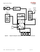
Figure 1 shows the current path for a normal Grid Tied Inverter from the PV solar panels through the
inverter, to the main service panel and on out to the grid. In a normal GTI application, power produced
from the PV array is consumed by loads connected to the main service panel with excess power going
out to the grid. However, with grid loss the GTI has no way to synchronize itself to the grid – a
requirement for operation – so it shuts down and is unable to use any potential energy from the PV array.
Figure 1 Normal GTI Power Flow