
GSLC175-PV1-120/240 Installation


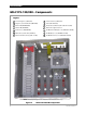

Table of Contents
2 900-0123-01-00 Rev C
Specifications ..................................................................................................... 51
Electrical Specifications ................................................................................................................................................... 51
Mechanical Specifications .............................................................................................................................................. 51
Regulatory Specifications ............................................................................................................................................... 51
Definitions ............................................................................................................................................................................ 52
Index ................................................................................................................. 53
List of Tables
Table 1 Size and Torque Requirements for Circuit Breakers and Bus Bars .................................... 19
Table 2 Terminal Bus Bar (TBB) Wire Size and Torque Requirements ............................................. 29
Table 3 Electrical Specifications ................................................................................................................... 51
Table 4 Mechanical Specifications .............................................................................................................. 51
Table 5 Terms and Definitions ..................................................................................................................... 52
List of Figures
Figure 1 GS Load Center (GSLC) ................................................................................................................. 5
Figure 2 GS Load Center with Devices ..................................................................................................... 6
Figure 3 GSLC Components ......................................................................................................................... 7
Figure 4 GSLC175-120/240 Components ................................................................................................ 8
Figure 5 GSLC175-230 Components ......................................................................................................... 9
Figure 6 GSLC175-PV-120/240 Components ....................................................................................... 10
Figure 7 GSLC175-PV-230 Components ................................................................................................ 11
Figure 8 GSLC175PV1-120/240 Components ...................................................................................... 12
Figure 9 GSLC175PV1-230 Components ............................................................................................... 13
Figure 10 Dimensions ..................................................................................................................................... 15
Figure 11 Knockouts and Mounting Holesfor Devices ....................................................................... 16
Figure 12 GSLC – Additional Components .............................................................................................. 17
Figure 13 GSLC175-120/240 and GSLC175-230 – Additional Components ................................ 17
Figure 14 Removing the Top Cover from the GSLC ............................................................................. 18
Figure 15 Removing the Front Door from the GSLC ............................................................................ 18
Figure 16 Removing the Interior Cover from the GSLC ...................................................................... 19
Figure 17 DC Positive Cable Plate (FW-BBUS) ........................................................................................ 19
Figure 18 Assembling the DC Positive (+) Cable Plate ........................................................................ 20
Figure 19 Inverter Bus Bars ........................................................................................................................... 21
Figure 20 Inverter Main DC Disconnects .................................................................................................. 22
Figure 21 DC Shunts ....................................................................................................................................... 23
Figure 22 Circuit Breakers ............................................................................................................................. 24
Figure 23 Mounting the GSLC ..................................................................................................................... 25
Figure 24 Mounting the Charge Controller to the GSLC Enclosure ................................................ 27
Figure 25 Mounting the HUB Product to the GSLC Enclosure .......................................................... 28
Figure 26 Grounding....................................................................................................................................... 29
Figure 27 Removing Bonding Connections ............................................................................................ 30
Figure 28 Battery Connections .................................................................................................................... 32