
Installation Guide


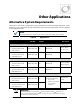

Other Applications
18 900-0184-01-00 Rev A
Positive Ground
The ICS Plus can be used in positive-grounded installations. For these solutions, the ungrounded PV
negative (–) conductors should be connected to the fuse holders. The grounded PV positive (+)
conductors should be connected to the white bus bar. Other connections, such as the combined PV
output, should be similarly reversed. The remaining combiner box connections are made as normal.
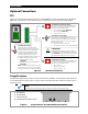
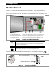
Figure 7 Positive-Grounded Combiner Box
IMPORTANT:
Some positive-grounded solutions require the disconnection of both the grounded and
ungrounded conductors. The ICS Plus product depicted here has only a single contactor.
It will not suffice for these applications.
IMPORTANT:
The ICS Plus product depicted here cannot be used in ungrounded systems.
The relay-trip breaker is wired differently from the method in the ICS Plus Quick Start Guide.
Figure 8 Positive-Grounded RTB
1 2
3
1
Positive Terminal Bus Bar Combines grounded (positive [+]) PV source and output circuits
2
PV Negative Output Terminal Connection for ungrounded (negative [–]) PV output circuit
3
PV Input Connections Connections for ungrounded (negative [–]) PV source circuits
LOAD (+)
LINE (–)
Combiner box PV negative (–)
Charge controller PV negative (–)