FLEXware Integrated Combiner Solution Plus Owner’s Manual
About OutBack Power Technologies OutBack Power Technologies is a leader in advanced energy conversion technology. OutBack products include true sine wave inverter/chargers, maximum power point tracking charge controllers, and system communication components, as well as circuit breakers, batteries, accessories, and assembled systems.
Table of Contents Important Safety Instructions .................................................................................. 4 Symbols Used ........................................................................................................................................................................ 4 General Safety .......................................................................................................................................................................
Table of Contents Important Safety Instructions READ AND SAVE THESE INSTRUCTIONS! This manual contains important safety instructions for the Integrated Combiner Solution Plus (ICS Plus) product. Symbols Used WARNING: Hazard to Human Life This type of notation indicates that the hazard could be harmful to human life. CAUTION: Hazard to Equipment This type of notation indicates that the hazard may cause damage to the equipment.
Introduction Audience This manual provides instructions for installation, setup, and operation of the product. These instructions are for use by qualified personnel who meet all local and governmental code requirements for licensing and training for the installation of electrical power systems with AC and DC voltage up to 600 volts. This product is only serviceable by qualified personnel.
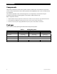
Introduction Components The primary component in the ICS Plus system is the DC combiner box. This combines up to six PV source circuits and provides an overcurrent protective device (OCPD) for each circuit. The AFCI device is located here. The combiner provides a local disconnecting means. It also provides a contactor for PV rapid shutdown functionality to de-energize PV circuits within 10 feet of the PV array.
Introduction PV Array Combiner ≤ 10 Feet Fuses AFCI Contactor ROOF HOUSE EXTERIOR Battery-Based Inverter HOUSE INTERIOR Charge Controller RSI Battery Bank Utility Meter RTB BKR-CTRL-DC Combiner Box Contains OCPD, AFCI, main contactor, PV Combiner Disconnect Includes local disconnect to de-energize PV circuits within 10 feet of the array Rapid Shutdown Initiator (RSI) Contains control circuit for PVRSS (contactors and relay-trip breakers) Includes PVRSS disconnect switc
Introduction Components NOTE: This manual depicts the use of a negative-grounded system. For positive grounding, see page 18.
Introduction RSI 1 2 5 3 5 4 5 1 Rapid Shutdown switch Initiates the PVRSS function; disconnects RTB and main contactor in combiner. 2 SOLAR ON indicator Green LED indicator; illuminates when DC voltage is present and Rapid Shutdown switch is in the ON position. 3 SOLAR OFF indicator Red LED indicator. SOLAR OFF must be illuminated to confirm PV shutdown. This indicator tells responders that the Rapid Shutdown switch is in the OFF position to create a “safe” condition.
Introduction This page intentionally left blank.
Functions Arc Fault Circuit Interruption In a PV system, an electrical arc occurs when current bridges a gap between conductive surfaces. Gaps can occur due to conductor damage, or can be caused by inadequate system connections. An “arc fault” is a safety concern for several reasons: Risk of electric shock if the mounting system or other components become electrified. Fire hazard due to heat buildup from the current flow. A series arc occurs across open connections in a single conductor.
Functions Arc Fault Self-Test The arc fault function can be manually tested. The arc fault self-test mimics the conditions of an arc fault. The combiner and RSI give the same indications as described on page 11. To perform the arc fault self-test: 1. Ensure the system is functioning and all indicators are normal. 2. Push the arc fault self-test button as shown in Figure 2 on page 8. 3. Listen for an audible click as the contactor opens. 4. Check the AFCI Annunciator on the combiner.
Installation This section assumes the use of the combiner, the RSI, the BKR-CTRL-DC and the RTB. The combiner box is a required part of all ICS Plus systems. All examples in OutBack literature show one or more combiners in use, including the ICS Plus Quick Start Guide. The RSI is required for all ICS Plus systems utilizing the PVRSS function. For examples of systems which may not require the use of the RSI, see page 17.
Installation Connection Information Combiner The combiner box can take input circuits from up to six PV subarrays. It provides a single PV output which is connected to the load center and one pole of the RTB. See Figure 4 on page 15. The combiner’s control board receives power from the RSI (2). It also sends status information to the RSI (3). Both sets of wires must be connected for correct PVRSS operation.
Installation 2 3 5 3 5 2 6 9 1 9 4 7 8 via load center 1 24V RSI Supply 5 PV RSI Safe 2 24V Combiner Supply 6 Breaker Trip 3 PV Arc Fault 7 Trip Sense 4 Breaker RSI Safe 8 Breaker-Trip Coil 9 PV to RTB Figure 4 900-0184-01-00 Rev A Block Diagram 15
Installation Optional Connections RSI The RSI has several sets of auxiliary terminals. Terminal J6 has a factory-installed jumper. J3, J4, and J5 do not. The terminals can be wired to alarms or switches to send or receive status messages. J3: AUX RSI Command/Status Output Dry contacts which report RSI status. The J3 contacts can activate a local alarm or send status messages to the Internet or other OutBack devices.
Other Applications Alternative System Requirements The ICS Plus can be used in systems with varying requirements, or with third-party equipment. Some systems may only need certain ICS Plus components, rather than the entire system. This may depend on the applicable codes. NOTE: All systems depicted here assume the use of a PV combiner with AFCI protection required.
Other Applications Positive Ground The ICS Plus can be used in positive-grounded installations. For these solutions, the ungrounded PV negative (–) conductors should be connected to the fuse holders. The grounded PV positive (+) conductors should be connected to the white bus bar. Other connections, such as the combined PV output, should be similarly reversed. The remaining combiner box connections are made as normal.
Troubleshooting LED Indicators Table 3 LED Table Box LED When Lit Notes RSI SOLAR ON (green) DC voltage present in system, Rapid Shutdown switch ON. May be lit at the same time as AFCI. Despite the label, SOLAR ON does not indicate that the PV system is active. It will illuminate even if PV is completely disconnected or if an arc fault is present. The name indicates to responders that this control does not shut down other parts of the electrical system; i.e. it only affects PV-related devices.
Troubleshooting Table 4 Troubleshooting Symptom Possible Cause Possible Remedy AFCI indicator and combiner AFCI Annunciator lit. Arc fault event. NOTE: The SOLAR ON indicator remains lit. If an arc fault is present, the shutdown of the system constitutes correct operation. The ICS Plus does not need troubleshooting. Investigate any potential causes throughout the PV system. Arc fault self-test button was pressed. Turn combiner disconnect switch or Rapid Disconnect switch off, then on.
Specifications Device Specifications Table 5 Electrical and General Specifications ICS Plus Combiner Box Device Rapid Shutdown Initiator Circuit Breaker Control Relay Trip Breakers Designation FWPV6-FH600-SDA RSI BKR-CTRL-DC PNL-75-DC-RT PNL-75D-DC-RT PNL-75Q-DC-RT Description 6-string combiner box with PV rapid shutdown, AFCI, and manual disconnect Initiates a PV rapid shutdown event; provides indication for PV status and AFCI DC breaker control and power supply; provides isolated 24 Vdc fro
Specifications Table 6 Mechanical and Environmental Specifications Device ICS Plus Combiner Box Rapid Shutdown Initiator Circuit Breaker Control Knockouts 2”, ½”, and ¾” ½” N/A Dimensions (H x W x D) Weight 15.5 × 19.5 × 4.5” (39.4 × 49.5 × 11.4 cm) ~ 12 lb (5.4 kg) 14.1 ×7.3 × 3.75” (30.5 × 17.8 × 12.7cm) ~ 4 lb (1.8 kg) Relay Trip Breakers N/A 2.0 × 5.25 × 4.4” (5.1 × 13.3 × 11.2 cm) Width only: PNL-75-DC-RT: 1.5” (3.9 cm) PNL-75D-DC-RT: 2.2” (5.7 cm) PNL-75Q-DC-RT: 3.8” (9.6 cm) 0.
Specifications Component Compliance The following individual components have been tested to comply with the following standards: Relay-Trip Breakers UL1077 Definitions The following is a list of initials, terms, and definitions used in conjunction with this product.
Masters of the Off-Grid.™ First Choice for the New Grid. Corporate Headquarters 17825 – 59th Avenue N.E. Suite B Arlington, WA 98223 USA +1.360.435.6030 900-0184-01-00 Rev A European Office Hansastrasse 8 D-91126 Schwabach, Germany +49.9122.79889.