FLEXware SkyBox Rapid Shutdown Solution Owner’s Manual
About OutBack Power Technologies OutBack Power Technologies is a leader in advanced energy conversion technology. OutBack products include true sine wave inverter/chargers, maximum power point tracking charge controllers, and system communication components, as well as circuit breakers, batteries, accessories, and assembled systems. Contact Information Address: Corporate Headquarters 17825 – 59th Avenue N.E. Suite B Arlington, WA 98223 USA Website: http://www.outbackpower.
Table of Contents Symbols Used ........................................................................................................................... 4 General Safety .......................................................................................................................... 4 Introduction .................................................................................................. 5 Audience ..........................................................................................
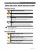
Important Safety Instructions READ AND SAVE THESE INSTRUCTIONS! This manual contains important safety instructions for the Rapid Shutdown Solution product. Symbols Used WARNING: Hazard to Human Life This type of notation indicates that the hazard could be harmful to human life. CAUTION: Hazard to Equipment This type of notation indicates that the hazard may cause damage to the equipment.
Introduction Audience This manual provides instructions for installation, setup, and operation of the product. These instructions are for use by qualified personnel who meet all local and governmental code requirements for licensing and training for the installation of electrical power systems with AC and DC voltage up to 600 volts. This product is only serviceable by qualified personnel. Welcome to OutBack Power Technologies Thank you for purchasing the FLEXware SkyBox Rapid Shutdown Solution (RSD-1).
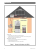
Introduction PV Array Combiner Fuse Contactors ≤ 10 Feet ROOF HOUSE EXTERIOR SkyBox Utility HOUSE INTERIOR Battery Bank RSI Meter o o Combiner Box Contains OCPD, main contactors, PV Combiner Disconnect Includes local disconnect to de-energize PV circuits within 10 feet of the array (required distance may vary with local code requirements) Rapid Shutdown Initiator (RSI) Contains control circuit for PVRSS (contactors and relay-trip breakers) Includes PVRSS disconnect switch Incl
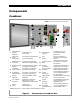
Introduction Components Combiner NOTE: All external wires are provided by installer 1 2 4 3 5 7 8 8 6 9 9 10 11 12 14 16 1 2 Gasketed Door/ Type 3R Enclosure Component Panel (Removable) 13 15 17 18 19 Ground Cable Terminal Provides “lay-in” lug for optional pass-through ground wire For ease of wire management 12 and for serviceability Fuse Holders PV source overcurrent protection; fuses provided by user Protects from the environment 11 3 Bidirectional PV Contactors Opens PV circuit
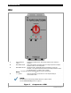
Introduction RSI 1 2 5 4 2 Rapid Shutdown switch SOLAR ON indicator 3 SOLAR OFF indicator 1 3 4 4 Initiates the PVRSS function; disconnects RTB and main contactor in combiner. Green LED indicator; illuminates when DC voltage is present and Rapid Shutdown switch is in the ON position. Red LED indicator. SOLAR OFF must be illuminated to confirm PV shutdown. This indicator tells responders that the Rapid Shutdown switch is in the OFF position to create a “safe” condition.
Introduction Functions Rapid Shutdown The rapid shutdown requirement is intended for firefighters or first responders. In an emergency, a responder may need to set the PV system in a “safe” (de-energized) state according to NEC 690.12. For this reason, the RSI is required to be mounted close to the main utility meter. The RSI must be easily visible. The RSI includes a Rapid Shutdown switch that initiates a disconnection of all elements of the PV system.
Introduction This page intentionally left blank.
Installation This section assumes the use of the combiner and the RSI. o The combiner box is a required part of all RSD-1 systems. All examples in OutBack literature show one or more combiners in use, including the Quick Start Guide. o The RSI is required for all RSD-1 systems utilizing the PVRSS function. Mounting Information The RSD-1 combiner box accommodates multiple mounting types. o It can be mounted horizontally, vertically, or at any intermediate angle.
Installation Surge Protector An optional surge protection device can be installed in the combiner. A knockout has been provided to accommodate this type of device. Figure 4 shows the underside of the combiner and the location of the knockout. NOTE: Any installed devices must be liquid-tight to sustain the combiner’s environmental rating. A. PV Conduit (2”) B. PV Cable Glands C. Surge Protector (½”) D.
Installation 1 1 2 4 4 1 1 3 2 1 PV Input 2 RSI Power Supply 3 Combiner Power Supply 4 PV RSI Safe NOTE: This is not a wiring diagram and does not serve in place of the installation instructions.
Installation Optional Connections RSI The RSI has several sets of auxiliary terminals. Terminal J6 has a factory-installed jumper. J3, J4, and J5 do not. The terminals can be wired to the SkyBox, or possibly other devices, to send or receive status messages. AUX RSI COMMAND/STATUS OUTPUT Dry contacts which report RSI status. The J3 contacts must be connected to the RSD INPUT terminals on the SkyBox.
Troubleshooting LED Indicators (RSI) LED When Lit Notes SOLAR ON (green) DC voltage present in system. Rapid Shutdown switch ON. Despite the label, SOLAR ON does not indicate that the PV system is active. It will illuminate even if PV is completely disconnected or if an arc fault is present. The name indicates to responders that this control does not shut down other parts of the electrical system. It only affects PV-related devices. SOLAR OFF (red) System is in “safe” mode. Rapid Shutdown switch OFF.
Troubleshooting Table 1 Troubleshooting Symptom Possible Cause SOLAR OFF indicator and another indicator both lit. RSI miswired. Check all wiring between RSI and combiner. SOLAR ON indicator lit, but charge controller does not register PV input. Combiner disconnect switch turned off. Turn on combiner disconnect switch. Array wiring error or poor connection. Check all PV wiring to combiner. Use DVM to confirm voltage of each subarray at combiner input terminals. Fuses blown in combiner box.
Specifications Device Specifications Table 2 Device Electrical and General Specifications Combiner Box Rapid Shutdown Initiator Designation FWPV3-FH600-SD2 RSI Description Combiner box with PV rapid shutdown and manual disconnect Initiates a PV rapid shutdown event; provides indication for PV status Compatibility Can accommodate 3 PV input strings per combiner Can control up to 6 combiner boxes #14 to #8 AWG (2.5 to 10 mm2) (Cable glands) #24 to #16 AWG (0.25 to 1.
Specifications Regulatory Specifications Listings This product carries a listing report by UL. It is listed to the following standards: o UL 1741 — Inverters, Converters, Controllers and Interconnection System Equipment for Use With Distributed Energy Resources (2nd Edition, 1/28/2010, with revisions through 3/23/2016) with PV Rapid Shutdown o CSA C22.2 — General Use Power Supplies, No. 107.
Specifications Definitions The following is a list of initials, terms, and definitions that may be used in conjunction with this product.
Masters of the Off-Grid.™ First Choice for the New Grid. Corporate Headquarters 17825 – 59th Avenue N.E.