
Installation Guide


Introduction
900-0236-01-00 Rev A
7
Components
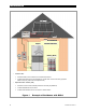
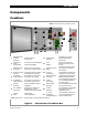
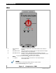
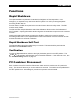
Combiner
Figure 2 Components of Combiner Box
1
Gasketed Door/
Type 3R
Enclosure
Protects from the
environment
11
Ground Cable
T
erminal
Provides “lay-in” lug for
optional pass-through
ground wire
2
Component
Panel
(Removable)
For ease of wire management
and for serviceability
12
Fuse
Holders
PV source overcurrent
protection; fuses provided
by user
3
Bidirectional PV
Contactors
Opens PV circuits for local
disconnect or rapid shutdown
13
Combiner Control
Board
Controls all functions within
the combiner; commands
the contactor
4
Ground Terminal
Bus Ba
r
Provides a means for system
and equipment grounding
14
PV Input
Connections
Connections for positive and
negative PV source circuits
5
PV Positive
Output Terminal
Connection on contactor for
PV positive output circuit
15
Communications
Terminals
Communicates with RSI and
additional combiner boxes
6
PV Negative
Output Terminal
Connection on contactor for
PV negative output circuit
16
2” EKO
(PV Output)
Accommodates conduit and a
UL 514-compliant fitting for
PV output circuits
7
Internal
Prewiring
Factory-installed for ease of
installation
17
Cable Glands
(PV Input)
Provide waterproof strain relief
for PV source circuits
8
PV Combiner
Disconnect
Activates the contactor for
disconnection; can be
padlocked in the OFF position
18
½” EKO
(optional)
For installation of a third-party
surge protection device
(provided by user)
9
Secu
r
e
Latch
Fastens door;
can be padlocked
19
½” and ¾”
(2 ea) EKO
(Communications)
Accommodate conduit and a
UL 514-compliant fitting for
communication wires
10
Securing Screw Secures door in place if padlock is not used
NOTE: All external wires are provided by installe
r
1 2 3
4 5
6
7
8
9
11
8
10
13
14
15
16
17 18
12
19
9