
2,800W 12V Manual


Installation
30
900-0166-01-00 Rev A
Multiple-Inverter AC Installations (Stacking)
Installing multiple inverters in a single AC system allows larger loads than a single inverter can handle.
This requires stacking. Stacking inverters refers to how they are wired within the system and then
programmed to coordinate activity. Stacking allows all units to work together as a single system.
Examples of stacking configurations include “series”, “parallel”, “series/parallel”, and “three-phase”.
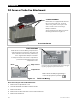
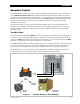
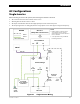
Figure 22 OutBack HUB10.3 and MATE3
Each inverter must be assigned a stacking mode, “master” or “slave”, depending on the configuration.
The master provides the primary output phase. Other inverters in the system base their phase on that of the
master. If the master shuts off, all other inverters also shut off. The master must sense and connect to an AC
source before other inverters can connect.
In a parallel-stacked system, the master tends to be the most heavily used unit.
“Subphase master” inverters are used in series or three-phase systems. A subphase master inverter operates
semi-independently of the master inverter. Although the master inverter sets the phase relationship, the
subphase master creates an output independent of the master.
The master on the L1 (or A phase) output cannot measure loads and voltages on any other output. The
subphase masters for the other outputs perform monitoring and regulation for the phase they control.
~ In a series or series/parallel-stacked system, a subphase master is required for the L2 output.
~ In a three-phase system, subphase masters are required for both the B and C phases.
A slave inverter does not create an independent output. It simply assists the master or subphase master by
adding power to the output as needed.
~ The Power Save function can place slave inverters in “Silent” mode when not in use. They are activated
by the master or subphase master when required.
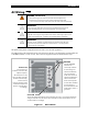
NOTE
: The FW-X240 and similar transformers are not used for load balancing of stacked FXR inverters.
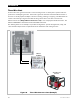
Each inverter is assigned to a particular phase when assigned a port on the HUB10.3 communications
manager. Port assignments will vary with the system. The master must be plugged into port 1. In
parallel stacking, any slave inverter can use any other port, beginning with port 2. In series or
three-phase stacking, the port assignments are very specific. See the HUB10.3 literature for more
information. Regardless, it is important to keep track of units and ports for programming purposes.
Programming uses the system display to assign a status and stacking value to the inverter on each
port. As long as the master is plugged into port 1, these assignments can be changed as needed.
MATE3
System
Display
Stacking Connections
Stacking requires an OutBack HUB10.3 communications manager and a system display.
Make all interconnections between the products with CAT5 non-crossover cable.
Additional Ports
Port 1
MATE
HUB10.3
Communications
Manager