
Outback FX-R Series Installation Manual


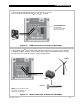

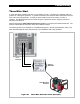

Installation
30
900-0166-01-01 Rev A
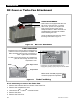
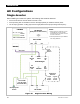
AC Configurations
Single-Inverter
When installing an inverter AC system, the following rules must be observed.
All overcurrent devices must be sized for 60 Aac or less.
All output wiring and circuit breakers must be sized appropriately for loads and inverter power.
The AC input (generator or utility grid) must be single-phase and the proper voltage and frequency.
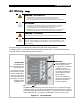
Figure 21 Single-Inverter Wiring
CAT5 Cable
AC Source
(Utility Grid or AC Generator)
AC Conduit
NEU GND
HOT
MATE3s
Inverter/Charge
r
AC
Neutral
IN
HUB/
MATE
Input
Circuit
Breake
r
AC
Neutral
OUT
AC
Hot
OUT
GROUND
Output
Circuit
Breaker
Bypass
Circuit
Breaker
Mechanical
Interlock
NEU GND HOT
AC Loads
Ground TBB
(may be within
AC Conduit Box)
Primary System
Ground
LEGEND
Ground
Hot
Neutral
TBB = Terminal Bus Bar
NOTES:
1. Neutral (common) conductor may be
connected from only one inverter
neutral terminal to a common bus bar
in the AC conduit box.
2. Colors depicted here may be different
from wiring standards.
AC
Hot
IN