
Outback FX-R Series Installation Manual


Commissioning
46
900-0166-01-01 Rev A
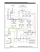
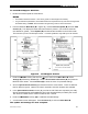
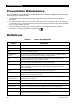
Figure 35 AC Terminals
3. Turn on the inverter using the system display (or external switch, if one has been installed). The
inverter’s default condition is Off. Do not turn on any AC circuit breakers at this time.
4. Using a DVM, verify 120 Vac (or appropriate voltage) between the AC
HOT OUT and AC
NEUTRAL OUT terminals. (See Figure 35.) The inverter is working correctly if the AC output
reads within 10% of 120 Vac or the programmed output voltage.
5. Proceed past the items below to Step 6 on the next page.
To start a multiple-inverter (stacked) system:
1. Close the main DC circuit breakers from the battery bank to the inverters. Repeat for every
inverter present. Confirm that the system display is operational.
With the system display, perform any programming for stacking and all other functions.
These functions may also include AC input modes, AC output voltage, input current limits,
battery charging, generator starting, and others. When stacking in parallel, all slave inverters
will observe the programming settings of the master inverter. They do not need to be
programmed individually. In a MATE3-class system display, the Profile Wizard may be used to
assist programming.
2. Turn on the master inverter using the system display (or external switch, if one was installed).
The inverter’s default state is Off. Do not turn on any AC circuit breakers at this time.
3. Using the system display, temporarily bring each slave out of Silent mode by raising the Power
Save Level of the master. (See page 43.)
As each slave is activated, it will click and create an audible hum. The green
S
TATUS
I
NVERTER
indicator LED on that slave will illuminate.
Confirm that the system display shows no fault messages.
4. Using a DVM, verify appropriate voltage between the AC HOT OUT terminal on the master
inverter and the AC
HOT OUT terminal on each slave. Series inverters should read within 10%
of 120 Vac or the programmed output voltage. Parallel inverters should read close to zero.
Three-phase inverters should read within 10% of 208 Vac or the designated output voltage.
5. When this test is finished, return the master to its previous Power Save Level.