
Outback FX-R Series Operator Manual


Operation
900-0167-01-01 Rev A
37
If installed in a system networked with a HUB Communications Manager, only a single RTS is
necessary. In most cases the RTS must be plugged into the master inverter. A system display
must be present for the compensation values to be shared to all devices.
NOTE
: In the FLEXmax 100 or FLEXmax Extreme charge controller, the rate of compensation
is adjustable. (See
Slope
below.) When changing the compensation rate in one of these
products, the RTS should be plugged into that controller, not the master inverter, to share the
new value with other devices. The communications manager and system display must still be
present to share the values.
IMPORTANT:
If the RTS is connected to an OutBack device other than those listed above, the compensation
values will not be shared.
If a system display is not connected, the compensation values will not be shared.
If the RTS is not connected to one of the charge controllers designated above, the controller’s
compensation values will not be shared.
See the applications note at www.outbackpower.com for more information on this topic.
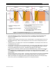
When charging, an inverter system with an RTS will adjust the charging voltage inversely with
changes in temperature. It will
increase
the charge voltage by 5 mV for every decrease of 1
degree Celsius per battery cell. Similarly, it will
decrease
the voltage 5 mV for every increase
of 1°C per cell.
This setting affects the
Absorption
,
Float
, and
Equalization
set points. The
Sell Voltage
and
Re-Float Voltage
set points are not temperature compensated. The
Equalization
set points
are not compensated in OutBack charge controllers.
In a 12 Vdc system (6 cells, 2 volts each), this means 0.03 volts per degree Celsius above or below
25°
C. Maximum compensation is ± 0.6 Vdc.
In a 24 Vdc system (12 cells, 2 volts each), this means 0.06 volts per degree Celsius above or below
25°
C. Maximum compensation is ± 1.2 Vdc.
In a 48 Vdc system (24 cells, 2 volts each), this means 0.12 volts per degree Celsius above or below
25°
C. Maximum compensation is ± 2.4 Vdc.
EXAMPLES
:
A 12 Vdc system with batteries at 10°C will compensate its charging to 0.45 Vdc
higher
than the
set point
s.
A 24 Vdc system with batteries at 35°C will compensate its charging to 0.6 Vdc
lower
than the
set point
s.
A 48 Vdc system with batteries at 15°C will compensate its charging to 1.2 Vdc
higher
than the
set point
s.
A 48 Vdc system with batteries at 40°C will compensate its charging to 1.8 Vdc
lower
than the
set point
s.
Slope
Some batteries require different amounts of compensation. The OutBack FLEXmax 100 and
FLEXmax Extreme charge controllers have an adjustable rate of compensation (“slope”) and
are not limited to 5 mV. The HUB Communications Manager can network these controllers with
the inverter. If this is done, the inverter can import the slope setting from the controller.
NOTE:
Temperature compensation only applies to the battery charging function. Other set points in
the inverter, such as the
A
UX
functions, are not compensated for temperature.