
Product Manual

Specifications
900-0169-01-00 Rev B 71
Calculating Limits
If other numbers are needed than those featured in Table 20, the results can be calculated. Do not use
the calculations on page 29, due to charger efficiencies and other factors.
To calculate the chargers and settings:
1. Look up the values for A, B, and C.
A = the battery bank’s maximum charge current (in Adc) from the battery manufacturer.
B = the maximum DC output of the appropriate inverter model. This is taken from Table 21.
C = the maximum AC input of the appropriate inverter model. This is taken from Table 21.
2. Select a value for D and perform the following calculation.
D = the
Charger AC Limit setting. This value must be 6 or higher. (See pages 44 and 69.) A higher
value uses fewer chargers and turns off all others. A lower value, or 6, leaves more chargers on.
3. Perform the following calculation.
__
A
__
(C) ÷ D = E
B
E = the number of chargers to use. This number should be rounded down in all cases.
4. Adjust the master inverter’s Charger AC Limit setting to equal D.
5. Turn off the chargers for all inverters that exceed E. In a system stacked on the HUB
communications manager, chargers on higher-numbered ports should be turned off first.
Chargers should be turned off by setting the Charger Control menu item to
Off. (See the menu
tables beginning on page 72 to locate this command in the menu structure.)
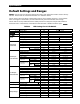
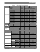
Table 21 Charge Currents for Calculations
Model Maximum DC Output (sent to battery) Maximum AC Input (used from source)
FXR2012E 100 Adc 7 Aac
VFXR2612E 120 Adc 9 Aac
FXR2024E 55 Adc 7 Aac
VFXR3024E 80 Adc 10 Aac
FXR2348E 35 Adc 7 Aac
VFXR3048E 40 Adc 10 Aac
Firmware Revision
This manual applies to inverter models with Revision 001.006.xxx or higher.
Updates to the inverter’s firmware are periodically available. These can be downloaded from the
OutBack website www.outbackpower.com. See page 49.