
Outback FX-R Series Installation Manual

Installation
36
900-0166-01-01 Rev A
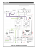
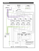
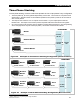
Figure 26 Parallel Wiring (Four Inverters)
NOTES:
1. Neutral (common) conductor may be
connected from only one neutral
terminal (per inverter) to a common
bus bar in the AC conduit box.
2. Colors shown here may be different
from wiring standards.
CAT5 Cables
AC Source
(Utility Grid or
AC Generator)
AC Conduit
Neutral
TBB
GND
Hot L1 TBB
MATE3s
AC
Neutral
IN
AC
Hot
IN (L1)
HUB/
MATE
Input
Circuit
Breaker
AC
Hot
OUT
GND
Output
Circuit
Breakers
Bypass
Circuit
Breakers
Neutral TBB
GND Hot L1
AC Loads
Ground TBB
(may be within
AC Conduit Box)
Primary
System
Ground
LEGEND
Ground
Hot L1
Neutral
TBB = Terminal Bus Bar
HUB 10.3
10 9 8 7 6 5 4 3 2 1 MATE
Input
Circuit
Breaker
AC
Neutral
IN
AC
Hot
IN (L1)
HUB/
MATE
L1 Slave
AC
Neutral
OUT
AC
Hot
OUT
GND
Inverter
L1 Maste
r
Inverter Inverter
L1 Slave
Inverter
L1 Slave
Input
Circuit
Breaker
Input
Circuit
Breaker
AC
Neutral
IN
AC
Hot
IN (L1)
HUB/
MATE
AC
Neutral
IN
AC
Hot
IN (L1)
HUB/
MATE
AC
Neutral
OUT
AC
Hot
OUT
GND
AC
Neutral
OUT
AC
Hot
OUT
GND
AC
Neutral
OUT
Mechanical
Interlock