USER MANUAL FOR: CFP20, BI16, CFP30, BI28, CFP2424, CFP1224, BI719, CFP1242, BI737, CFP1264, BI757, CFP1272, BI766, CFP1284, BI778, CFP1296, BI790, CFP12108, BI7102, CFP12120, BI7114 AND CUSTOM LINEAR BURNERS CAUTION ! • Important operating instructions included. • Read, understand, and follow these instructions for safe installation and operation. ! INSTALLER: Leave manual with the appliance. CONSUMER: Retain this manual for future reference.
DANGER: FLAMMABLE GAS UNDER PRESSURE. LEAKING LP-GAS MAY CAUSE A FIRE OR EXPLOSION IF IGNITED CAUSING SERIOUS BODILY INJURY OR DEATH. CONTACT LP GAS SUPPLIER FOR REPAIRS, OR DISPOSAL OF A CYLINDER OR UNUSED LP-GAS. WARNING: FOR OUTDOOR USE ONLY.* DO NOT USE OR STORE CYLINDER IN A BUILDING, GARAGE, OR ENCLOSED AREA. WARNING: Know the odor of LP-gas. If you hear, see, or smell leaking LP-gas, immediately get everyone away from the cylinder and call the Fire Department.
1 Additional Warnings ! This appliance is a Decorative Outdoor Gas Appliance for OUTDOOR USE ONLY and MUST NOT be used for cooking. Install the burner system in an enclosure on a flat and stable surface in an outdoor location such as a patio or deck. This location must be adjacent to the gas supply line or propane gas supply. DO NOT locate the appliance where it will get excessively wet or submerged in water.
TABLE OF CONTENTS 1. Appliance Information a. Appliance Certification b. Specifications 2. Getting Started a. Included Items b. Tools and Supplies Required c. Inspect the Appliance and Components 3. Appliance Clearance Requirments a. Surrounding Clearances b. Enclosure Clearances for CFP Models c. Enclosure Clearances for BI Models 4. Enclosure Design Requirements a. Self-Contained Propane Cylinder Installations b. Hard-Piped Propane Installations c. Hard-Piped Natural Gas Installations 5.
1 APPLIANCE INFORMATION A. APPLIANCE CERTIFICATION MODEL: ALL CRYSTAL FIRE® PLUS BURNERS & BURNER INSERTS TESTING AGENCY: Underwriters Laboratories (UL LLC) TYPE: Decorative Gas-Fired Outdoor Fireplace. STANDARD: ANSI Z21.97-2017 / CSA 2.41-2017 Outdoor Decorative Gas Appliances The Crystal Fire® Plus burner series has been tested in accordance to ANSI Z21.97-2017 / CSA 2.
MODEL ORIFICE SIZE MAXIMUM INPUT RATE PROPANE NATURAL GAS PROPANE NATURAL GAS CFP20* BI16* CFP2424* #36 (Burner) #21 (Burner) Low: 26K BTU/hr. (7.62 kW) Low: 25.5K BTU/hr. (7.47 kW) #52 (Valve) #43 (Valve) High: 73.5K BTU/hr. (21.5 kW) High 77.5K BTU/hr. (22.12 kW) CFP1224* BI719* #36 (Burner) #21 (Burner) Low: 25K BTU/hr. (7.32 kW) Low: 25.5K BTU/hr. (7.47 kW) #52 (Valve) #43 (Valve) High: 75K BTU/hr. (21.98 kW) High 75.5K BTU/hr. (22.12 kW) CFP1242* BI737* .
2 GETTING STARTED A. INCLUDED ITEMS 1. Crystal Fire® Plus Burner 4 ! 2. Crystal Fire® Plus Instruction Manual 3.
B. TOOLS AND SUPPLIES REQUIRED 1. Work Gloves 2. Safety Glasses 2 3. Utility Knife (for opening packaging) 4. (2X) Adjustable Wrenches 5. 11mm Wrench (for NG conversion only) 3 1 4 6. 10mm Wrench 7. Phillips Screwdriver 7 8. Flat-Blade Screwdriver (for NG conversion only) 9. Corrosion-free Leak Test Solution 5 10 8 6 9 10. (1X) AAA Battery C. INSPECT THE APPLIANCE AND COMPONENTS What to inspect: 1. Burner • Look for bent or dented components. IGNITION WIND GUARD BURNER TRIM 2.
3 APPLIANCE CLEARANCE REQUIREMENTS A. SURROUNDING CLEARANCES ! WARNING ! ! FIRE RISK WARNING ! FOR OUTDOOR USE ONLY Follow all minimum clearance requirements. Failure to provide adequate clearance to combustible materials can result in property damage or loss of life. Appliance should be installed in an enclosure in a location that meets the following criteria: • Easy access to appliance control panel. • Easy access to gas connections for service and maintenance.
B. ENCLOSURE CLEARANCES FOR CFP MODELS ! WARNING ! Follow all minimum clearance requirements. Failure to provide adequate clearance to combustible materials can result in property damage or loss of life. A Required Clearances to Combustibles LINEAR MODELS A B C 4 in. 4 in. 4 in. CFP1224 B CFP1242 CFP1264 CFP12120 CFP1272 CFP1284 CFP1296 CFP12108 C Required Clearances to Combustibles A SQUARE MODELS A B C CFP2424 4 in. 4 in. 4 in.
C. ENCLOSURE CLEARANCES FOR BI MODELS ! WARNING ! Follow all minimum clearance requirements. Failure to provide adequate clearance to combustible materials can result in property damage or loss of life. Required Clearances to Combustibles A LINEAR MODELS A B C 7 in. 7 in. 4 in. BI719 B BI737 BI757 BI7114 BI766 BI778 BI790 BI7102 C Required Clearances to Combustibles A ROUND MODELS A B C BI16 6.75 in. 6.75 in. 6 in. BI28 6 in. 6 in. 6 in. B C 42508 REV G CFP : 12-01-2020 www.
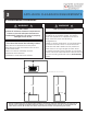
4 ENCLOSURE DESIGN REQUIREMENTS A. SELF-CONTAINED PROPANE CYLINDER INSTALLATIONS The Outdoor GreatRoom CompanyTM has vent blocks available for DIY landscape block projects as well as vent plates for other enclosures. See reference materials for more information. OPENINGS ARE SHOWN AS 5" X 2" RECTANGLES. 5.00 MAXIMUM 5.00 MAXIMUM All Dimensions are in Inches MINIMUM VENTILATION REQUIREMENTS: Two (2) openings of equal size on opposite sides of the enclosure.
B. HARD-PIPED PROPANE INSTALLATIONS The Outdoor GreatRoom CompanyTM has vent blocks available for DIY landscape block projects as well as vent plates for other enclosures. See reference materials for more information. OPENINGS ARE SHOWN AS 5" X 2" RECTANGLES. 5.00 MAXIMUM All Dimensions are in Inches MINIMUM VENTILATION REQUIREMENTS: Two (2) openings of equal size on opposite sides of the enclosure. The top of these openings should be within 5 in.
C. HARD-PIPED NATURAL GAS INSTALLATIONS The Outdoor GreatRoom CompanyTM has vent blocks available for DIY landscape block projects as well as vent plates for other enclosures. See reference materials for more information. OPENINGS ARE SHOWN AS 5" X 2" RECTANGLES. 5.00 MAXIMUM All Dimensions are in Inches MINIMUM VENTILATION REQUIREMENTS: Two (2) openings of equal size on opposite sides of the enclosure. The bottom of these openings should be within 5 in.
5 GAS SETUP AND INFORMATION ! WARNING: ! FIRE AND EXPLOSION RISK: VERIFY INLET PRESSURES • High pressure may cause an over-fire condition. • Low pressure may cause delayed ignition and explosion. • Minimum pressure must be verified when ALL household appliances are operating. AN APPLIANCE REGULATOR MUST BE INSTALLED UPSTREAM OF THE APPLIANCE FOR ALL PRESSURES ABOVE 14 IN. WC FOR LIQUID PROPANE AND ALL PRESSURES ABOVE 11 IN. WC FOR NATURAL GAS. A.
D. LEAK CHECK AND LINE PURGE Once the gas piping system is in place, all fittings and connections need to be checked for leaks. Use a commercially-available, non-corrosive leak check solution. Once leak test is complete, be sure to rinse off all remaining leak check solution from the gas piping systems. ! WARNING: CHECK FOR GAS LEAKS ! FIRE RISK EXPLOSION RISK ASPHYXIATION RISK • Check all fittings and connections. • Do not use an open flame.
6 BURNER INSTALLATION A. SELF-CONTAINED PROPANE CYLINDER INSTALLATIONS ! A YouTube tutorial on self-contained propane cylinder setups is available at this web address: WARNING ! Installation and repair should be performed only by a qualified service technician. https://www.youtube.com/watch?v=h2wflGK6RdY&feature=youtu.be IMPORTANT Other media options apart from the supplied clear glass gems can be used in Crystal Fire® Plus burners, but they should be supplied by the Outdoor GreatRoom CompanyTM.
4. Secure control valve to control panel with two (2) supplied Phillips head screws. Install control knob onto valve stem. See Image 6.4. 5. Connect igniter and ground wire to sparker box. See Image 6.5. Both wires can connect to either connection point. The unit will operate in either configuration. (Img. 6.4) 6. Carefully uncoil thermocouple and connect to control valve. Hand-tighten first then securely tighten (1 thread visible) with 10 mm wrench. See Image 6.6.
8. Press and hold the sparker button to verify presence of spark. Look inside ignition wind guard for visible spark. See Image 6.8. LOOK FOR SPARK HERE DEPRESS SPARKER BUTTON 9. Ensure propane cylinder valve is closed. Hand-tighten propane regulator hose to propane cylinder. See Image 6.9. (Img. 6.8) SEE DETAIL HAND-TIGHTEN SECURELY TURNING CLOCKWISE 10. Verify that control valve is in OFF position. Apply commercially-available, non-corrosive leak check solution to all gas connection points.
B. HARD-PIPED PROPANE INSTALLATIONS ! WARNING ! Installation and repair should be performed only by a qualified service technician. 1. Secure supplied control panel to enclosure with suitable fasteners. See Image 6.12. If installing into an Outdoor GreatRoom CompanyTM fire table, a control panel will already be installed and the supplied control panel can be discarded. A control panel for use in landscape block applications is available. See Reference Materials for information. (Img. 6.12) 2.
5. Secure control valve to control panel with two (2) supplied Phillips head screws. Install control knob onto valve stem. See Image 6.16. 6. Connect igniter and ground wire to sparker box. See Image 6.17. Both wires can connect to either connection point. The unit will operate in either configuration. 7. Connect main gas supply to ½” male flare fitting of control valve using adjustable wrenches. See Image 6.18. Smooth copper pipe is suggested for best operation.
9. Carefully place burner assembly into enclosure. Evenly spread glass media over burner surface. Glass media CANNOT be present inside igniter wind guard. Glass media CAN cover ignition wind guard cover. See Image 6.20 for proper media coverage. Remove cardboard cover from inside ignition wind guard.
C. HARD-PIPED NATURAL GAS INSTALLATIONS ! WARNING ! Installation and repair should be performed only by a qualified service technician. 1. Secure supplied control panel to enclosure with suitable fasteners. See Image 6.24. If installing into an Outdoor GreatRoom CompanyTM fire table, a control panel will already be installed and the supplied control panel can be discarded. A control panel for use in landscape block applications is available. See Reference Materials for information. (Img. 6.24) 2.
NATURAL GAS CONVERSION INSTRUCTIONS: 5. Using 11 mm wrench, remove low-rate bypass tube from control valve. See Image 6.28. 6. With a flat-blade screwdriver, remove valve orifice and replace with natural gas orifice specified on Pg. 6 of this manual. If no valve orifice is required, low-rate bypass tube can be reinstalled using 11 mm wrench. See Image 6.29. (Img. 6.28) 7. Using adjustable wrenches, remove burner flex-line from burner orifice.
10. Secure control valve to control panel with two (2) supplied Phillips head screws. Install control knob onto valve stem. See Image 6.32. 11. Connect igniter and ground wire to sparker box. See Image 6.33. Both wires can connect to either connection point. The unit will operate in either configuration. 12. Connect main gas supply to ½” male flare fitting of control valve using adjustable wrenches. See Image 6.34. Smooth copper pipe is suggested for best operation.
14. Carefully place burner assembly into enclosure. Evenly spread glass media over burner surface. Glass media CANNOT be present inside igniter wind guard. Glass media CAN cover ignition wind guard cover. See Image 6.36 for proper media coverage. Remove cardboard cover from inside ignition wind guard.
18. If no leaks are present, a first lighting and final leak check can be performed. With main gas supply shut-off valve open, turn control valve to LOW/IGNITION position. Press and hold sparker button, slowly depress control knob. Hold knob in for 3-5 seconds. See Image 6.39. Burner should be ignited. Verify no bubbles are present on outlet side of gas system. OFF HOLD KNOB IN FOR 3-5 SECONDS ROTATE COUNTER-CLOCKWISE TO LOW AND SLOWLY DEPRESS LOW/ IGNITION HIGH PRESS AND HOLD SPARKER BUTTON (Img. 6.
7 LIGHTING AND OPERATION ! WARNING ! OFF FIRE OR EXPLOSION HAZARD LOW/ IGNITION If you do not follow these instructions exactly, a fire or explosion may result causing property damage, personal injury, or loss of life. HIGH PUSH AND HOLD TO IGNITE 1. Verify control valve is in OFF position. See Image 7.1. If operating on a self-contained propane cylinder, ensure cylinder valve is CLOSED.
8 TROUBLESHOOTING SYMPTOM 1. Burner will not ignite POSSIBLE CAUSES A. Propane tank is empty. Replace propane tank with full tank or have propane tank filled and reattempt ignition. B. Propane tank OPD has been activated. This occurs when the Propane tank is full and the Propane tank valve is opened without first closing the appliance control valve. Close propane tank valve and disconnect propane regulator hose from tank. Reconnect propane regulator hose to tank and open valve.
4. 5. 6. 7. During operation, metallic pinging noises are occurring. A. Different thermal expansion rates of different components. A. Over time, the tempered glass media supplied with the appliance can Normal use over a long period of time. break down. Replacement glass can be installed after damaged glass is removed. B. Excessive thermal shock (abrupt temperature changes) over a short period of time. Avoid dumping of liquids (beverages) into appliance.
9 SERVICE AND MAINTENANCE A. REGULAR MAINTENANCE TASKS If using a self-contained propane gas supply system with the supplied propane regulator hose assembly, the hose should be inspected for damage BEFORE EACH USE OF THE APPLIANCE. If damage to the hose is present, do not operate the unit and contact the dealer or location from which the product was purchased for a replacement propane regulator hose. ! WARNING ! Installation and repair should be performed only by a qualified service technician.
B. CLEANING THE APPLIANCE 1. Remove glass media and clean in basin of water mixed with dish soap. Allow to dry on a towel. BURNER TRIM BURNER SURFACE 2. Use compressed air to remove any debris from the burner surface. See Image 9.4. 3. Stainless steel burner trim can be cleaned and polished with commercially-available stainless steel cleaners and a polish such as BrassoTM. See Image 9.4. (Img. 9.4) 32 www.outdoorrooms.
10 REFERENCE MATERIALS A. SERVICE PARTS LIST 4 1 8 5 2 6 7 9 3 13 10 # 11 12 14 15 Part Description Part Number Variable Control Safety Valve For CFP1224, CFP20, CFP2424 VCSV-S Variable Control Safety Valve For CFP1242, CFP30 VCSV-L 2 ½” Female Flare X 3/8” Male Flare Adapter 050-F-FL-0375-M-FL 3 20 lb.
B.
C. DIMENSIONAL INFORMATION All Dimensions are in Inches 21.06 19.38 15.87 14.97 CFP20 BI16 32.00 27.95 30.04 25.32 CFP30 BI28 23.66 23.66 25.60 25.60 23.66 25.60 42508 REV G CFP : 12-01-2020 CFP2424 www.outdoorrooms.
All Dimensions are in Inches 19.63 17.24 25.63 23.68 11.56 13.50 CFP1224 BI719 42.52 11.56 13.50 BI737 57.00 55.87 64.30 36 5.04 7.42 62.36 CFP1264 7.42 36.52 34.00 40.58 CFP1242 5.04 11.56 13.50 www.outdoorrooms.com BI757 5.17 7.
All Dimensions are in Inches 72.00 70.06 66.00 63.75 CFP1272 11.56 13.50 5.17 7.42 BI766 84.00 82.06 CFP1284 78.00 75.75 11.56 13.50 BI778 5.17 7.42 96.00 94.06 90.00 87.75 11.56 CFP1296 42508 REV G CFP : 12-01-2020 13.50 www.outdoorrooms.com BI790 5.17 7.
All Dimensions are in Inches 108.00 102.00 106.06 CFP12108 99.75 11.56 13.50 5.17 7.42 BI7102 120.00 114.00 118.06 111.75 CFP12120 38 11.56 13.50 www.outdoorrooms.com BI7114 5.17 7.
11 WARRANTY INFORMATION The Outdoor GreatRoom CompanyTM extends the following warranty for Outdoor GreatRoom outdoor products used in the United States of America or Canada. Dealers and employees of The Outdoor GreatRoom CompanyTM have no authority to make any warranty or authorize any remedies in addition to or inconsistent with the terms of this warranty. This warranty gives you specific legal rights. You may also have other rights that vary from state to state.
PRODUCT CATEGORY WARRANTY INFORMATION Limited lifetime warranty on all stainless steel burners installed in a residential setting, and 5 years on all stainless steel burners installed in a commercial setting.
42508 REV G CFP : 12-01-2020 www.outdoorrooms.