
Direct Spark Ignition Manual


35
www.outdoorrooms.com
42519 REV D DSI : 03-16-2021
B. REMOTE PAIRING AND OPERATION
Close main gas supply shuto valve.
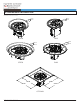
Open DSI control box by rotating the locking
tabs as shown. See Image 10.8.
Using a small at-blade screwdriver, carefully
unscrew INLET pressure tap on gas control
valve. See Image 10.9.
Place a ¼” (6 mm) ID rubber tube over the
pressure tap and connect to a manometer. This
manometer should be able to accurately read
pressures between 0 and 14 in.
WC (0 kPA and 3.5 kPa).
Slowly open main gas supply shuto valve
and turn control switch of appliance to the ON
position. See Image 10.10. With appliance in
operation, the pressure reading can be taken.
If gas pressure is not ideal with the unit in
operation, adjust the gas supply regulator until
the gas pressure reading is ideal. See table on
Pg. 5.
Turn control switch to the OFF position, close
the main gas supply shuto valve, and remove
rubber tube from pressure tap. Then close
pressure tap with small at-blade screwdriver
and secure cover on DSI system.
Open main gas supply shuto valve. Appliance
is ready for normal operation.
1.
2.
3.
4.
5.
6.
7.
8.
(Img. 10.9)
(Img. 10.10)
(Img. 10.8)
SEE DETAIL A
SEE DETAIL B
SEE DETAIL A
INDICATOR LIGHT
LEARN BUTTON
WARNING
!
!
Pressure testing should be performed only by
SEE DETAIL A
INLET PRESSURE TAP