9x6 Cabana Assembly Manual Version #1.4 June 16, 2022 Thank you for purchasing a 9x6 Cabana. Please take the time to identify all the parts prior to assembly. Note: The General Assembly Manual illustrates a Door Configuration in the front center location. The Door can also be positioned in the front corners. To correctly configure Door in front corners, follow general assembly steps and refer to Page 37 for required changes.
What to do before my Shed arrives? • Become familiar with this assembly manual and determine if you can complete the project yourself or will require a professional contractor. • One helper is recommended to assist in constructing your shed. It generally takes two people over two days to assemble a shed. If you’re hiring a contractor, their rate should be in line with that duration of work. • Clear the construction area and ensure a clear pathway for delivery when the freight company arrives.
Foundation Types for a 9x6 Garden Shed 75” 75” 6” Deep 105” 105” Completed Foundation Concrete Foundation Floor Frame Concrete Slab Foundation: - Slab must be at least the same size as assembled floor frame (75” x 105”) or larger. - 6” Deep foundation. - 1.0 Cubic Yards of concrete required. - A concrete slab will have the longest durability out of your foundation options. Once level, a concrete slab is the easiest surface to build on.
Thank you for purchasing our 9x6 Cabana. Please take the time to identify all the parts prior to assembly. D. Trim and Miscellaneous Section Parts List: Bottom Skirting 10 - 1/2” x 4 1/2” x 34 3/4” - Bottom Skirting A.
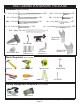
9X6 CABANA HARDWARE PACKAGE Hardware Kit (Provided) x 255 S1 - 2 1/2” Screws x 25 SS2 - 3/4” Screws Silver x 152 S3 - 2” Screws x6 SB1 - 3/4” Screws Black Headed x 32 SB2 - 2” Screws Shingle x 185 S2 - 1 1/4” Screws x 51 N2 - 1 1/2” Nails Black Headed x 355 N1 - 1 1/2” Nails Finishing x2 BR1 - Square Drive Bit Single Rafter Bracket x 6 Drop Latch Tee Hinge x4 Door Handle Silver Barrel Bolt Ridge Board Connector x 2 Tools Required Hammer 90° Metal Bracket x 8 (Not Provided) Tape
Regular Maintenance & Tips to prolong the life of your shed. Before/During Assembly: 1.) Paint each face and edge of your plywood floor with a latex exterior paint. 2.) Caulk wall seams if gaps appear. 3.) Caulk around window framing. 4.) Caulk perimeter between floor plywood and bottom wall plate. 5.) Caulk channels in lap siding at the top of your door above the trim, just a drop in each channel. 6.) Caulk edge of door threshold (if applicable). 7.
A. Floor Section Exploded view of all parts necessary to complete Floor Section. Identify all parts prior to starting. Plywood Floor Large (2) Plywood Floor Small Floor Joist (4) Floor Joist Frames (3) Concrete Pad (optional foundation method) Floor Runners Long (3) Floor Runners Short (3) You can find the Square Drive Bit for the screws in with the Hardware Kit Bag. Inside Frame to Inside Joist 10 3/4 ” 13 1. Attach Interior Floor Joists to Floor Joist Frames.
17 1/2” 2. Both Outside Floor Joist Frames require 1 Floor Joist attachment. Center Joist 17 1/2” from Outside of Floor Joist Frame and attach with 2 - 2 1/2” Screws per end. Center Frame 3. Position completed Floor Joist Frames with center frame in the middle. Attach the Floor Joist Frames together with 6 - 2 1/2” Screws per section. When completed, your floor joist section should be 105” wide x 75” deep. 75” 105” Short Runner Long Runner Centered Short Runner Flush with Floor Framing 4.
Concrete Slab Foundation 5. With Floor Runners attached, carefully flip the floor over and place on your foundation. Caution: you will need 2 people to assist you. Be careful when laying floor down not to bend or twist floor. When in place, level floor completely. Foundations Note: The floor will be flipped over and floor runners will sit on your foundation. It is important to note that having a level foundation is critical. Choosing a foundation will vary between regions.
Important: The following steps in assembly are shown with bevel sided walls. Assembly instructions for different siding types are interchangeable. B. Wall Section Exploded view of all parts necessary to complete the Wall Section. Identify all parts prior to starting. Side Gable Wall Panel (2) Front and Rear Top Wall Plate (4) (Angle cut down length) Side Top Wall Plate (2) (Angle cut on end) Door Header Solid Wall Panel (7) Window Wall Panel (2) Vertical Door Jamb (2) Bottom Wall Plates (7) 8.
Important: Pilot hole ALL 2x3 Wall Studs with 1/8” drill bit prior to screwing. This will make it much easier to attach together. Pilot Hole first. Wall Plate Parts Hardware Solid Wall Panels S1 - 2 1/2” Screws face down. Position and attach a Bottom Wall Plate to (35” x 75”) x 7 x 21 total bottom of wall studs of each wall panel with 3 - 2 1/2” Bottom Wall Plates Screws. Position so plates are flush with framing. (1 1/2” x 2 1/2” x 35”) x 7 9. Starting with Solid Wall Panels, carefully lay panel 10.
rear wall side wall 2 1/2” Screws Pilot Hole first. Optional - Caulking seams will help prevent moisture from entering your shed. Caulking not included in kit. Side Wall Panel 12. Position 1st side wall panel on plywood floor so once again 2x3 bottom wall plate is sitting flush with floor framing. Position panel so vertical 2x3 framing sits flush with rear wall framing.When both wall panels are positioned correctly, attach together at top, middle and bottom of vertical studs with 3 - 2 1/2” Screws.
16. Complete attachments of remaining side walls as per Steps 11 - 15. Pilot Hole first. 17. Position and attach both Window Walls as per Steps 11 - 15. Parts Hardware Window Walls S1 - 2 1/2” Screws (35” x 75”) x 2 x 6 total Flush to edge of wall siding Parts Hardware Vertical Door Jambs S1 - 2 1/2” Screws wall studs with 4 - 2 1/2” Screws per Jamb. Position so (1 1/2” x 3 1/8” x 73”) x 2 x 8 total jamb is flush with tip of bevel siding on front window walls. 18.
Notch to front and on top. Parts Door Header side. Header is 3 1/8” wide at bottom and has a 1/2” thick x 2 1/2” wide strip of (2” x 3 1/8” x 35”) x 1 wood stapled to the top creating a notch or dado effect. This notch needs to be positioned on the top facing the front. The notch is necessary as the roof Hardware panel may hang up on the header and must sit flush on the rafter tops when S1 - 2 1/2” Screws attached. Screw from door header into door jambs with 4 - 2 1/2” Screws x 4 total (2 per side).
Optional - Caulking seams will help prevent moisture from entering your shed. Caulking not included in kit. Pilot Hole first. Angle screws into perimeter Floor Joists. 32” Hardware S1 - 2 1/2” Screws of wall frames should sit flush with outside of floor framing, with siding overhanging x 36 total by approximately 1/2”. Confirm 32” wide door opening at bottom. When positioned correctly, fasten bottom wall plates to floor using 4 - 2 1/2” Screws per wall panel. 20.
Front Top Plate 22. Next, attach the Front Top Plates. The Front and Rear Top Plates are angle cut down the length. Once again, position Top Plates on wall frame so they are flush. Front and Rear Top Plates will fit between Side Top Plates. Attach with 4 - 2” Screws per plate. Complete all other Side & Rear Top Plate attachments. 23. Place Side Gable Wall so 1x3 framing sits flush with the inside of the Top Plate. It should also be centered sideways on the Top Plate. Adjust Gable accordingly.
C. Rafter and Roof Section Exploded view of all parts necessary to complete the Roof Section. Identify all parts prior to starting. Filler Shingles (16) Outside Roof Panels (2) Middle Roof Panels (2) Outside Roof Panels (2) Ridge Boards (4) 44” and 61” long Metal Ridge Board Connectors (2) Roof Rafters (9 per side) 18 total Soffits (4) 90° Metal Brackets (8) Rafter Brackets Double (4) Single (6) Roof Gussets (3) Metal Ridge Board Connector 8 - 3/4” screws Ridge Board Ridge Board 25.
26. Locate 9 Rafters, 2 Soffits and a completed Ridge Board. Lay out on level ground as shown to the right. Double up Rafters as illustrated. Screw doubled up Rafters together with 3 - 2 1/2” Screws per piece.
Ridge Board Sof fit 29. Flip Rafter Section over so Soffit is facing down. Starting with the rear Section, lift completed rafters up and place on gable framing. Gable Notch Ri Ra fte r dg 30. e Bo ar d Slide Rafter Section up on gable framing until bottom of Ridge Board slips into gable notch. Soffit should sit approx. 1/8” away from wall panel. 31.
32. Place front completed Rafter Section on gable walls as per Steps 30 & 31. rd e dg Ri a Bo Gable Notch Offsetting Metal Ridge Board Connectors. 33. 34. With both Ridge Boards connected, At the peak, align Ridge Boards so they are flush together and secure them with 12 - 1 1/4” Screws. Important: if there is a gap between Ridge Boards, have a helper push the front and rear walls closer together from outside. Walls should be 70” apart at top from inside of wall plate to opposite wall plate.
s os ” 70 r Ac Roof Gussets are positioned on mid rafters. Have two helpers push the Parts (Steps 35 - 36) Roof Gussets Front and Rear Walls at the top from the outside of shed until inside to inside (3/4” x 3 1/2” x 48”) x 3 measurement between the Top Plates is 70”. Slide Gusset up on side of Rafters. Hardware (Steps 35 - 36) Gusset must be below top edge of Rafter. Use level to square Gusset and attach S3 - 2” Screws to Rafters with 4 - 2” Screws. Pilot hole each Gusset end with 1/8” drill bit.
Exploded view of upside down roof panels. Shingles overhang plywood on outside panels. Outside Roof Panel. Shingles and plywood flush on middle panel. Identify all Roof Panels. There are 4 Outside Parts (Steps 38 - 42) Hardware (Steps 38 - 42) Outside Roof Panels S1 - 2 1/2” Screws and 2 Middle Roof Panels. Outside Panels will have (41” wide) x 4 x 12 total shingles overhanging the plywood on one end. Lift up Middle Roof Panels and place an Outside Roof Panel on Rear Rafters. (35” wide) x 2 38.
Shingles overhang plywood on Outside Roof Panel. 41. Lift up, position and attach 2nd Outside Roof Panel on Rafters as per Step 39. Middle Panel Outside Panel Outside Panel 42. Position and attach Front Roof Panels as per Steps 38 - 41. 43. Roof Filler Shingles are included to cover roof seams. Starting at the bottom, slide the first Long Shingle in until flush with other bottom shingles.
Attach above the exposure line. Exposure Line 44. Screw first filler shingle down to rafters using 1 - 2 1/2” Screw per panel (2 in total). Make sure to screw into both rafters. 45. Slide in another filler shingle and attach as per Step 44. On your last row of shingles, attach smaller filler shingle with 2 - 1 1/2” Shingle Nails near the top, to be covered by Ridge Caps in Step 59. Complete all four rows of filler shingles where roof seams meet in the same way. 46.
D. Miscellaneous Section Exploded view of all parts necessary to complete the Miscellaneous Section. Identify all parts prior to starting.
g tin fron e t sk 48. Attach Bottom Skirting around the base of the shed. Skirting will hide floor framing. Gaps on side will be covered by Wide Trim pieces later. Start with Front and Rear Skirting pieces first and attach with 4 - 1 1/2” Finishing Nails per piece. sid irtin ir sk g Parts Bottom Skirting (1/2” x 4 1/2” x 34 3/4”) x 10 Hardware N1 - 1 1/2” Finishing Nails x 40 total Gap between Filler Trim. Trim to top of wall. Flush to bottom of wall siding. 49.
Fit Corner Trim tight underneath Soffit. Wide Corner Trim Corner Trim 50. To trim out corners, start with a Corner Trim, align tight underneath Soffit and Rafter. Align Wide Corner Trim with bottom of Corner Trim. Corner Trim will cap the Wide Corner Trim. Do a dry run in each corner before attaching to confirm positioning. Use 8 - 1 1/2” Finishing Nails per piece to secure. Complete other front corner the same.
51. Trim out rear corners with remaining pieces of Corner Trim and Wide Corner Trim. Align and attach with 8 - 1 1/2” Finishing Nails per piece as per Step 50. Align with top of Wide Corner Trim. Butt up tight to side of Wide Corner Trim. 52. Attach Horizontal Gable Trims to both sides of shed (2 per side). Position over flashing where the gables and walls meet. Butt ends tight against Wide Corner Trims and align tops together.
53. Attach Rear Wall Narrow Trim where wall panels come together and leave a seam. Position trim equally on wall seam and tight underneath Soffit and Rafter. Use 8 - 1 1/2” Finishing Nails per piece to secure. Parts Rear Wall Narrow Trim (1/2” x 2 1/2” x 79”) x 2 Hardware N1 - 1 1/2” Finishing Nails x 16 total Align with bottom of Horizontal Gable Trim. Parts Attach both Side Wall Narrow Trims Side Wall Narrow Trim where wall seams come together on sides.
55. Attach Facia Nailing Strips to the underside edge of the plywood roof. Align corner of Nailing Strip with corner of roof plywood. Secure each Strip with 3 - 1 1/4” Screws. Complete all four pieces, two on each side of the shed. Parts Facia Nailing Strips (3/4” x 2 1/2” x 44 1/2”) x 4 Hardware S2 - 1 1/4” Screws x 12 total Flush with corner of roof plywood. Parts Attach Side Facia to end of roof panel plywood and Nailing Side Facia - Angle Cut Ends Strip.
cia a eF Sid 57. Attach Front and Rear Facia to rafter ends. There are 2 Facia pieces per side. Secure with 8 - 1 1/2” Finishing Nails per piece, ensure nails connect with the ends of the rafters behind Facia. Gaps between facia pieces will be covered by Detail Plates in Step 58. Parts Front & Rear Facia (3/4” x 3 1/2” x 57 1/4”) x 4 Hardware N1 - 1 1/2” Finishing Nails x 32 total Pentagon Facia Detail Plate Front Facia caps Side Facia. Horizontal Gable Detail Plate 58.
d en m fro 59. 8” Place 1st Roof Ridge Cap on roof peak overhanging shingles by approximately 1”. Attach with 2 - 1 1/2” Shingle Nails 9” from end. Place 2nd Ridge Cap 1” back from 1st cap. Attach with 2 - 1 1/2” Shingle Nails 9” from end. 9” Important: Butt (thick) end of Ridge Cap will be facing towards the outside of shed. Parts (Steps 59 - 60) Roof Ridge Caps x 18 Hardware (Steps 59 - 60) N2 - 1 1/2” Shingle Nails x 38 total 8” 60.
61. Position Vertical Door Trim pieces flush with inside edge of Door Jambs and tight to Soffits on top. Attach with 8 - 1 1/2” Finishing Nails per piece. Flush with inside of door jamb. Parts Vertical Door Trim (1/2” x 3 1/2” x 79”) x 2 Hardware N1 - 1 1/2” Finishing Nails x 16 total oor Trim Horizontal D 62. Attach Horizontal Door Trim with 4 - 1 1/2” Finishing Nails to cover Door Header.
2“ Screws 3/4” screw Top Door Bottom Door Top and Bottom Hinges centered on door trim. 63. Vertical Door Trim Attach Door Hinges to Top and Bottom Dutch Door sections. Top Door has trim overhanging door at bottom while bottom door has trim recessed slightly. Hinges should be centered on door trim with barrel nudged to end of trim. Use 2” & 3/4” Black Headed Screws as shown above.
1/4” gap on inside. Slight gap.Top Trim overlaps bottom trim to prevent water from getting in. 65. Place the Top Dutch Door Panel into place and gap top and bottom trims on the outside about 1/8” apart. On the inside, horizontal door frames should be about 1/4” apart. Use a shim once again to help you. Attach hinges to trim with 2” Black Headed Screws provided. 2” Screws Important: Drill pilot holes with 1/8” drill bit prior to securing with screws to prevent wood splitting.
Temporarily position Interior Vertical Door Stop to help align Interior Barrel Bolt. Silver Barrel Bolt 67. Attach Interior Silver Barrel Bolt to inside of door as illustrated above. Use 3/4” Silver Screws to secure. Refer to Step 68 to allow for adequate clearance. 68. Attach Interior Door Stops to door framing (Jambs and Header). Start with Vertical Door Stops. Stops should overlap doorway by 1/2”. Use 4 - 1 1/4” Screws to secure each piece. Attach Horizontal Door Stop next using 3 - 1 1/4” Screws.
Window frame. Caulk gap. Screw insert into thick part of siding. Parts To reduce possible water from penetrating Window Inserts x 2 into the window cavity, caulk gap on both sides of window opening prior to installing Window Hardware Insert. Position insert in cavity and screw with S2 - 1 1/4” Screws 6 - 1 1/4” Screws. x 12 total 69. Caulk gap. 70. Once Insert is attached, Trim dado caulk the “channel gap” between the Insert’s outside flange and the siding.
72. Assemble Flower Box with Assembly Instructions included on Page 40. Position completed Flower Box below bottom of window trim and secure with 2 - 2” Screws per box. Screw from inside of box into the center wall stud. Attach second screw 2” underneath first screw and once again into the wall stud. Install Flower Box Kits underneath each window. Parts Hardware Flower Box Kits x 2 S3 - 2” Screws x 4 total Toll Free 1-888-658-1658 www.outdoorlivingtoday.com Page 38 sales@outdoorlivingtoday.
Alternate Door Configuration (Door on Left or Right of Center) To configure the Cabana so the Door is positioned on the left or right of center wall panel, follow the general directions in this manual for a regular door configuration and note the following changes. A. Follow sequential Steps 9 - 17 in the Wall Section for regular configuration to position and secure wall panels. For Door on left side, align and attach two Window Wall Panels in center and right positions.
Outdoor Living Today Flower Box Assembly Instructions Side Trims (D) Exploded View Front Trim (C) End Caps (B) 1 1/4” Nails (G) Parts Lists: A - Base, Rear & Front Box Frames (3pcs) 3/4” x 5 1/2” x 23” B - End Cap Frames (2pcs) 3/4” x 5 1/2” x 7” / 8” C - Front Trim (1 pc) 3/4” x 1 1/2” x 26” D - Side Trims (2 pc) 3/4” x 1 1/2” x 8 3/4” E - Brackets (2 pc) 1 1/2” x 5 1/2” x 5 1/2” F - 1 1/4” Screws G - 1 1/4” Nails Front (A) Flush Rear (A) Brackets (E) Right Angle Cut to Rear Fro nt ) r (A ea R
Congratulations on assembling your 9x6 Cabana! Note: Our Sheds are shipped as unfinished products. If exposed to the elements, the western red cedar lumber will weather to a silvery-gray color. If you prefer to keep the cedar lumber looking closer to the original color, we suggest that you treat the wood with a good oil base wood stain. You may also wish to paint your new shed rather than stain it.