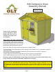
8x8 Gardener’s Shed Assembly Manual Version 13 Feb 12th, 2015 Thank you for purchasing an 8x8 Gardener’s Shed. Please take the time to identify all the parts prior to assembly. Safety Points and Other Considerations Our products are built for use based on proper installation and normal residential use, on level ground. Please follow the instruction manual when building your shed and retain the manual for future maintenance purposes.
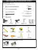
Thank you for purchasing our 8x8 Gardener’s Shed. Please take the time to identify all the parts prior to assembly. Parts List: A. Floor Section 2 2 2 2 4 5 - 45 1/2” x 75” - Floor Joist Frames 45 1/2” x 21” - Floor Joist Frames 45 1/2” x 75” - Plywood Floor - Large 45 1/2” x 21” - Plywood Floor - Small 1 1/2” x 3 1/2” x 72” - Floor Joists 1 1/2” x 3 1/2” x 60” & 31” Floor Runners B.
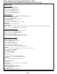
8x8 GARDENER HARDWARE SHEET Hardware Kit (Provided) Note: screws and nails shown actual size.
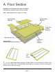
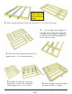
A. Floor Section Exploded view of all parts necessary to complete Floor Section. Identify all parts prior to starting. Note: Floor Footprint is 96” wide x 91” deep. Plywood Floor Small (2) Plywood Floor Large (2) Floor Joist Frames Small (2) Floor Runners (10) Floor Joist Frames Large (2) Concrete Pad (optional foundation method) Flush with framing 1. Lay out Large Floor Joist Frame and 2 Floor Joists as illustrated above. Position Joists equally in Floor Joist Frame.
You can find the Square Drive Bit for the screws in with the Hardware Kit Bag. 2. When correctly positioned, attach each Joist with 4 - 2 1/2” screws (2 per end). 3. Lay out Floor Joist Frames as illustrated at left. There are 2 larger and 2 smaller Frame Sections. The Footprint for the floor when attached together will be 96” wide x 91” deep. 4. Attach each large and small floor joist frame together with 6 - 2 1/2” screws per section. 91” 96” 5. Complete all large and small frame 6.
7. Attach Floor Runners to completed floor frame. There are 2 floor runners per 91” side and 5 completed runners in total. Use 3 - 2 1/2” screws per Runner. 8. Make sure Runners are flush with outside and front and rear floor framing but not overhanging. Concrete Slab Foundation 10. With Floor Runners attached, carefully flip 9. Complete all Floor Runners. Foundations Note: The floor will be flipped over and floor runners will sit on your foundation.
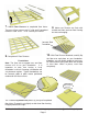
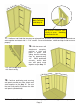
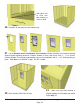
12 . With Plywood positioned correctly on floor framing, attach with 1 1/4” screws. Use screws every 16”. Hint: Use a chalk line to mark location of floor joists to determine screw placement. B. Wall Section Exploded view of all parts necessary to complete the Wall Section. Identify all parts prior to starting. Front and Rear Top Plates (3 per side) Gable Walls (4) 2 Angle cut on 1 end and 1 square cut.
14. Lay out all the wall panels and become familiar with their location. On a Standard Kit, there is 1 Window Wall Panel, 6 Solid Wall Panels and 1 Narrow Wall Panel. Make sure to position panels right side up so water is directed away from and not into shed. Compare siding with window wall panel to determine proper wall orientation. Fro nt Important: Make sure all walls are aligned in their upright position. If not, water may leak into your shed.
all W d i Rea ol eS Sid r So lid W all Do Not Attach Walls To Floor Until Step 23. Optional - Caulking seams will help prevent moisture from entering at seam. Caulking not included in kit. 17. Position a 2nd Solid Wall into place on plywood floor. Butt both vertical wall studs of side and rear walls together and attach with 3 - 2 1/2” screws. Screw at the bottom, middle and top of stud to secure properly. ar Re 18.
Wall panel will sit flush with floor framing at Front of shed. Front of She d 20. Complete all side and rear wall attachments. 21. Locate Window Inserts and Window Trim Packages. Before installing, run a bead of caulking around window opening perimeter. Position window in cavity and secure with 8 - 1 1/4” screws. Position Window Trim around window doing a dry run first and attach with 4 - 1 1/2” finishing nails per piece. Trim Sizes = 1x 24 1/16” = top / 3 x 23” = sides. 23.
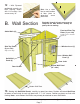
24. Position and attach Narrow Wall Panel to left side wall stud with 3 - 2 1/2” screws as per Step 17. Note: Narrow Wall is 73” high (2” shorter than wide walls). Siding overhangs adjacent wall stud and floor. Jamb sits flush with outside of siding. 25.Locate Vertical Door Jamb and position flush against right wall panel stud. The Jamb is 3” wide and will sit flush to outside of wall siding. When positioned correctly, secure Jamb using 4 - 2 1/2” screws.
Optional: Caulking seams will help prevent moisture from entering at seam. Caulking not included in kit. Bottom Wall Framing Ca ulk ing 27. When all walls are attached together, check alignment with the floor. Bottom wall framing should sit flush with outside of floor joists. Confirm 32” wide door opening at bottom. When positioned correctly, fasten bottom wall plates to floor using 4 - 2 1/2” screws per wall panel. Angle screws into perimeter Floor Joists. Doorway Opening is 32” 28.
Si de To p e p To t n Pl ate at Pl o Fr 29. Next, attach the 2 Side Top Plates (1 per side). The side top plates are angle cut down the Edge. Once again, position top plate on wall plate so it is flush with inside of wall framing. Side plate should also be flush with Front Top Plate. Secure with 4 - 2” screws per piece. Rear Top Plates 30. Position the Rear Top Plates on back wall to complete as per Step 28. Use 4 - 2” screws per piece.
32. Lift up a completed gable section and place on top of Rear Top Plate on wall. The rear gable framing should sit flush with the inside of the top plate. straight edge Flashing overhangs wall siding. 33. The gable should be centered sideways (left to right) on the top plate. Hint: use a straight edge to check the angle of the gable framing and top plate. Both angles should line up. Adjust gable accordingly. Temporarily attach Gable to walls and top plate with 2 - 2” screws.
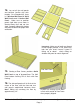
C. Rafter and Roof Section Exploded view of all parts necessary to complete the Roof Section. Identify all parts prior to starting. (Roof Filler Shingles Missing) Front Roof Panels (2) Rear Roof Panels (2) Roof Rafters (12) Ridge Boards (4) Metal Ridge Board Connectors (2) Roof Gussets (2) Soffits (4) 1/2” x 4 1/2” x 45 1/2” 3/4” thick Ridge Board 8 - 3/4” screws 35. Locate 3/4” x 4 1/2” x 57 1/2” & 33 1/2” Ridge Boards and attach together with Metal Ridge Board Connector using 8 - 3/4” screws.
36. Locate 6 - 1 1/2” x 3 1/2” x 56 1/2” long Rafters, 2 - 1/2” x 4 1/2” x 45 1/2” long Soffits and completed Ridge Board from Step 35. Lay out as illustrated on a flat level surface. 56 1/2” Rafters Ridge Board Important: Pilot Hole Ridge Board to prevent splitting! 4 1/2” wide Soffits Important: Pilot Hole Soffit to prevent splitting! Ridge Board 37. Attach end of a 45 1/2” long Soffit Board flush to ends of outside rafter with 2 - 1 1/4” screws per rafter end.
Ri dg e Bo ar d Soffit er Raft Gable Notch 39. Flip Rafter Section over so Soffit is facing down. Starting with the left side, lift completed rafter section up and place on gable framing. 40. Slide Rafter Section up on gable framing until bottom of Ridge Board slips into gable notch. Rafter should rest on gable framing 41. When Rafter Section is correctly positioned, outside rafters will sit equally on gable framing and Soffit will sit approximately 1/8” away from wall panels.
Gable Notch Metal Offsetting Ridge Board Connectors d ar e dg Ri Bo Rafter 43. At the peak, align Ridge Boards so they are flush together and secure them with 8 - 1 1/4” screws. To completely secure Ridge Boards, place 4 - 1 1/4” screws into any of the remaining Metal Ridge Board Connector holes. Complete both sides. Important: if there is a gap between Ridge Boards, try pushing side walls closer together from outside. Walls should be 91” apart at top from inside of wall plate to wall plate. 44.
91 ”a cro ss 45. Secure Rafters to Top Wall Framing with one 3” screw per rafter. Screw through Wall Frame at an angle. Have two helpers push the side walls at the top from the outside of shed until inside to inside measurement between the side plates is 91”. 46. Roof Gussets are positioned on both mid rafters. Slide gusset up, use level to square gusset and attach to rafters with 4 - 2” screws. Pilot hole each Gusset end with 1/8” drill bit. Complete remaining Gusset.
1 - 2 1/2” Screw in Bottom Row of Shingles Roof Plywood flush with rafter end. Angle Screw from Rafter into Plywood. 48. Place Roof Panel so it sits flush on 3rd rafter from the outside (doubled up rafter). Plywood on roof should be flush with end of rafter at bottom. From the outside, screw down through bottom row of shingles into rafter with 1 - 2 1/2” screw. Angle a 2 1/2” screw from outside rafter into roof plywood. 1 - 2 1/2” Screw 49.
Attach above the exposure line. Exposure Line 51. Roof Filler Shingles are included to cover roof seams. Starting at the bottom, slide the first Long shingle in until flush with other bottom shingles. 53. Slide in another Long Filler Shingle and attach as per Step 52. On your last row of shingles, the filler shingle is precut to fit properly. Attach to roof with 2 Shingle Nails per shingle. 52. Screw first filler shingle down to rafters using 1 - 2 1/2” screw per panel (2 in total).
D. Miscellaneous Section Note: missing from exploded drawing: Interior Door Stops. Exploded view of all parts necessary to complete the Miscellaneous Section. Identify all parts prior to starting.
Expert Advice: When installing trim, sort pieces according to color and pieces that are most pleasing to the eye. Start with least visible side and use the least desirable pieces first. Install trim to most visible sides as your skill installing trim improves. ng 57. om ott Attach Filler Trim (4 - 1/2” x 2 1/2” x 75”) to front and rear walls in each corner. Hammer with 8 - 1 1/2” finishing nails. Strips are positioned flush with siding and bottom skirting.
60. Attach Narrow Rear Wall Trim (1 - 1/2” x 2 1/2” x 77 1/2”), where rear wall panels come together and leave a seam, with 8 - 1 1/2” finishing nails. Align Trim at bottom with the corner trims. Angled Facia Narrow Trim Square Cut Facia An gl ed Fa cia acia are Squ F Cut Square cut Facia positioned between Angled Facia 61. Position Front and Rear Facia (angle cut on ends) and Side Facia (square cut on ends) in corner. Line Fascia up so square cut Facia is positioned between angled cut facia.
64. Narrow Trim Position the 2 remaining Narrow Trim (2 - 1/2” x 2 1/2” x 77 1/2”) pieces flush with inside of door jamb. To determine vertical height of trim, do a dry run with Horizontal Gable Trim in Step 65. Make sure Gable Trim covers flashing and mark. Attach Trim with 8 - 1 1/2” finishing nails. cover gable flashing Wide Trim Flush with inside of Door Jamb. Small gap Hor. Ga ble Trim 65. Attach Horizontal Gable Trim ( 4 - 1/2” x 4 1/2” x 44 1/2”) to Front and Rear of shed.
Important: Butt (thick) end of Ridge Cap will be facing towards the outside of shed. 9” from end 67. Place First Roof Ridge Cap on roof peak overhanging shingles by approximately 2”. Attach with 2- 1 1/4” Shingle Nails 9” from end. Place 2nd Ridge Cap 1” back from 1st cap. Attach with 2- 1 1/4” Shingle Nails 9” from end. 8” 8” 68. Place 3rd Ridge Cap 8” back from 2nd (enough to cover shingle nails). Attach 3rd Ridge Cap down as per Step 67.
2” Black Screws Approx. 1/4” gap 1-3/4” Black Screw 71. Door Panel should be positioned so there is 1/4” gap at top. Use a shim once again to help you position door correctly. Attach top and middle hinge to narrow trim with hinge hardware provided. 2” Black Screws 72. Attach Black Barrel Bolt as illustrated above with 2” & 3/4” Black Screws. Note how female part of Barrel Bolt is positioned higher than male. Do a dry run first to position Barrel Bolt correctly.
Congratulations on building your 8x8 Gardener’s Shed! Note: Our Sheds are shipped as unfinished products. If exposed to the elements, the western red cedar lumber will weather to a silvery-gray color. If you prefer to keep the cedar lumber looking closer to the original color, we suggest that you treat the wood with a good oil base wood stain. You may also wish to paint your new shed rather than stain it.