6x6 Maximizer Storage Shed Assembly Manual Architectural Knotty with Plywood Roof Version #18 July 13, 2021 Thank you for purchasing a 6x6 Maximizer Storage Shed. Please take the time to identify all the parts prior to assembly. Please Note- Roofing Shingles are NOT included in this kit. You will be required to purchase approximately 60 Square Feet of shingles along with the appropriate hardware to fasten shingles to plywood roof sheathing.
What to do before my Shed arrives? • Become familiar with this assembly manual and determine if you can complete the project yourself or will require a professional contractor. • One helper is recommended to assist in constructing your shed. It generally takes two people over two days to assemble a shed. If you’re hiring a contractor, their rate should be in line with that duration of work. • Clear the construction area and ensure a clear pathway for delivery when the freight company arrives.
Foundation Types for 6x6 Garden Shed 70” 6” Deep 70” 75” 75” Front Side Front Side Front Side Concrete Foundation Completed Foundation Floor Frame Concrete Slab Foundation: - Slab must be at least the same size as assembled floor frame (70” x 75”) or larger. - 6” Deep foundation. - 0.7 Cubic Yards of concrete required. - A concrete slab will have the longest durability out of your foundation options. Once level, a concrete slab is the easiest surface to build on.
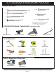
Thank you for purchasing a 6x6 Maximizer Storage Shed Please take the time to identify all the parts prior to assembly. Parts List: A. Floor Section 2 2 4 3 - 35” x 75” - Floor Joist Frames 5/8” x 34 7/8” x 74 7/8” - Plywood Floor 1 1/2” x 3 1/2” x 72” - Floor Joists 1 1/2” x 3 1/2” x 70” Floor Runners B.
6 x 6 MAXIMIZER HARDWARE PACKAGE Screws and Nails 2 1/2” x160 2” x100 2” x38 x120 1 1/4” x30 3” x26 3/4” Black Headed 1 1/2” Finishing Nail x250 Black Headed x1 Square Drive Bit Individual Hardware Components Door Handle x2 Exterior Barrel Bolt (not actual size) Tee Hinge x6 Cane Bolt Tools Required Hammer Level Screw Gun/Drill Pliers Tape Measure Ladder Wood Clamp 1/8” & 1/2” Drill Bits Safety Equipment Required Safety Glasses Toll Free 1-888-658-1658 Work Gloves www.
Regular Maintenance & Tips to prolong the life of your shed. Before/During Assembly: 1.) Paint each face and edge of your plywood floor with a latex exterior paint. 2.) Caulk wall seams if gaps appear. 3.) Caulk around window framing. 4.) Caulk perimeter between floor plywood and bottom wall plate. 5.) Caulk channels in lap siding at the top of your door above the trim, just a drop in each channel. 6.) Caulk edge of door threshold. 7.) Optional: Install a Sill Gasket between floor runners and foundation. 8.
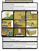
A. Floor Section Exploded view of all parts necessary to complete Floor Section. Identify all parts prior to starting. Note, Floor Footprint is 70” wide x 75” deep. Plywood Flooring (2) Floor Joists (4) Floor Joist Frames (2) Concrete Pad (optional foundation method) Floor Runners (3) Flush with framing 1. Lay out one Floor Joist Frame and 2 Floor Joists as illustrated above. Position Joists equally in Floor Joist Frame. Position Joist so flush with framing. Toll Free 1-888-658-1658 www.
You can find the Square Drive Bit for the screws in with the Hardware Kit Bag. 2. When correctly positioned, attach each Joist with 4 - 2 1/2” screws (2 per end). Complete Joist attachments for 2nd Floor Frame. 3. Lay out both completed Floor Joist Frames as illustrated at left. 4. Align Floor Joist Frames together as shown below. Screw Sections together with 8 - 2 1/2” screws. 5. When completed, your floor footprint Door goes on 70” side should be 70” wide x 75” deep.
6. Attach Floor Runners to completed floor 7. Make sure Runners are flush with outside and frame. There are 3 floor runners per 70” side. Use 8 - 2 1/2” screws per Runner. front and rear floor framing but not overhanging. 2” 1/ Foundations Note: The floor will be flipped over and floor runners will sit on your foundation. It is important to note that having a level foundation is critical. Choosing a foundation will vary between regions.
Completed Floor 11. With Plywood positioned plywood pushed together at seam. correctly on floor framing, attach using 16 - 1 1/4” screws per sheet. B. Wall Section 75” 70” Door goes on 70” side Exploded view of all parts necessary to complete the Wall Section. Identify all parts prior to starting.
Plywood Floor shown in Floor Section B illustrations may not be exactly as shipped. 13. Lay out all the wall panels and become familiar with their location. Make sure to position panels right side up so water is directed away from and not into shed. Note, to determine correct alignment, the attached Bottom Wall Plate of wall panel will be sitting on floor. Fr on t Door Jamb Door Header 14. Starting at Rear Corner, position a Wall Panel on top of plywood floor.
Optional - Caulking seams will help prevent moisture from entering at seam. Caulking not included in kit. Vertical Wall Stud 16. Position side wall into place on plywood floor. Butt both vertical wall studs of side and rear walls together and attach with 3 - 2 1/2” screws. Screw at the bottom, middle and top of stud to secure properly. Re ar Wa ll l de al W Si Do Not Attach Walls To Floor until Step 27. 17. With the corner wall attachment complete, position a second side wall panel in place.
Re ar W all Pa ne ls ls ll Pane a W e Sid 18. Align vertical wall studs of both side wall panels together and attach with 3 - 2 1/2” screws. Wall siding should overhang floor by approximately 1/2”. Position 2nd rear wall panel as previously described. Re ar W all ing Wall panel framing aligned flush with floor framing. r ide o Flo m Fra Re ar S 19. Align wall panel framing flush with floor framing and attach vertical wall studs together as per Step 18. Sid eW all P ane 20.
Outside of Jamb flush with outside of siding 21. Locate Door Jambs. Position outside of Jamb flush with outside of siding. At the floor, Jamb should be flush with floor framing on the front and overhanging floor framing on sides. When aligning Jambs and Header in Steps 21-23, do a dry run first to confirm spacing. Tack jambs with only a few screws initially. Jambs should be 64” apart when measured inside to inside. 22. Attach Door Jamb to vertical wall stud with 4 - 2 1/2” screws.
On ends, screwing on slight angle provides more strength Top Plate aligned flush with inside of wall framing. 24. Position one Side Top Plate (angle cut on both ends) on top wall framing. Top Plate should be evenly spaced from front to back and aligned flush with the inside of wall framing. Attach into wall framing with 4 - 2” screws. 25. Position a Front Top Plate (angle cut on edge) on to top of wall framing. Butt the straight cut end up to Side Top Plate and align flush with the front of Door Header.
26. Complete remaining Side and Rear Top Plate attachments as per Steps 24-25. Important: Prior to fastening walls and installing rafters, take time to confirm your walls are level, square and plumb. Measure diagonal at top and bottom of walls corner-to-corner. This should be approximately 95 1/2”. More importantly, if measurements are not within 1/4”, your walls are not square. Adjusting now will make it easier to install the roof section later. Angle screws into perimeter Floor Joists. 27.
Straight Edge 1x3 Gable Framing Gable Flashing 28. Place Gable so framing sits flush with the inside of the top plate. Center from front to rear using a Straight Edge to confirm angle of gable frame and Top Plate line up. Adjust gable accordingly. From the outside, make sure gable flashing overhangs wall siding. 29. Temporarily attach Gable to walls and top plate with 2 - 2” screws. Screw from the bottom of gable framing down into Top Plate and Wall.
C. Rafter and Roof Section Exploded view of all parts necessary to complete the Roof Section. Identify all parts prior to starting. Plywood Roof Panels (2) 78” x 45 1/4” Ridge Boards (2) 3/4” x 4 1/2” x 70” Roof Gusset Roof Rafters (12) Soffits (2) 1/2” x 4 1/2” x 70” 3/4” thick Ridge Board 45” Long Rafters 31. Locate 6 Roof Rafters @ 1 1/2” x 3 1/2” x 45”, 1/2” thick Soffit Toll Free 1-888-658-1658 1 Ridge Board @ 3/4” x 4 1/2” x 70” and 1 Soffit @ 1/2” x 4 1/2” x 70”.
32. Attach Ridge Board to ends of both outside rafters with 2 - 2” screws per end. Drill 1/8” pilot holes in Ridge Board to prevent splitting. Measure and position interior Rafters as illustrated below. Double up center rafters and screw together with 2 - 2 1/2” screws first. When positioned correctly, attach Ridge Board to remaining rafters with 2 - 2” screws per rafter end.
35. Starting at the rear and with a helper, flip a completed rafter section over and lift up and place rafter section on gable wall framing. Soffit Ridg e Bo ar d Rafter should rest on gable framing Ra fter Gable Notch 36. Slide rafter section up on gable framing until bottom of ridge board slips into gable notch. 37. When rafter section is correctly positioned, outside rafters will sit equally on gable framing and soffit will sit approximately 1/8” to 1/4” away from wall panels.
Rid ge Bo ard Screw Ridge Boards together with 1 1/4” screws 95 1/2” Rafter Gable Notch. 39. With ridge board locked into gable notch, align ridge boards so they are flush together and secure them with 8 - 1 1/4” screws. Important - if there is a gap between Ridge Boards, try pushing rear wall and Door Header closer together from outside. Before moving on with further steps, confirm your shed is square at wall height by checking the diagonal distance of the top walls on the inside.
70 ” 42. The Roof Gusset 1- 3/4” x 3 1/2” x 48” is positioned on center rafter. Use level to square gusset and attach to rafter with 4 - 1 1/4” screws. Pilot hole Gusset to prevent splitting. If we required, have a helper(s) push at the front and at the rear near the top of the walls from the outside of shed until inside to inside measurement between the top plates is 70” before attaching. 4” overhang past Rafter. 4“ Flush with end of Rafter. Evenly positioned on Interior Rafter 43.
Not past apex 44. When Plywood is correctly positioned, fasten down into Roof Rafters with 15 - 1 1/4” screws. 45. Locate Plywood Roof Piece for the rear side (78” x 45 1/4”). 46. Position and attach as per Steps 43- 45. Toll Free 1-888-658-1658 www.outdoorlivingtoday.com Page 23 sales@outdoorlivingtoday.
D. Miscellaneous Section Exploded view of all parts necessary to complete the Miscellaneous Section. Identify all parts prior to starting.
Additional 1 1/2” nails in each corner to secure wall siding to framing. 49. Attach Side and Rear Skirting around the base 48. Position Front Skirting (3/4” thick) between Door Trims aligning it even at top edge with floor. Use 6 - 1 1/2” nails to secure. 50. of the shed. Skirting will hide floor framing. The side skirting pieces will meet together in the center. Gaps on outside will be covered by Wide Trim pieces later. Use 4 - 1 1/2” nails to secure.
Side Rear Wide Trim sk irt ing Align trim tight underneath Soffit and Rafter. 52. Attach Narrow Trims (Rear Walls) to in each rear corner and middle wall seam (3 - 1/2” x 2 1/2” x 79”). Use 8 - 1 1/2” finishing nails per piece. Align Trims tight underneath Soffit and Rafter and so it caps the Side Rear Wide Trim. 53. Position and attach Side Front Wide Trims and Narrow Trims (Sides). Use 8 - 1 1/2” nails per piece to secure. Narrow Trim Cover wall seam Side Front Wide Trim Detail Plate 54.
55. Attach Facia Nailing Strips (4 - 3/4” x 1 1/2” x 42”) to underside edge of plywood roof with 4 - 1 1/4” screws per piece. Do this on both sides of the shed. Locate Side Facia (angle cut on both ends). There are 2 left and 2 right side pieces. Correct positioning is rough side out. Starting on one side, line facia up so the end is even with edge of plywood roof. Attach to nailing strip with 8 - 1 1/2” nails. Align 2nd Side Facia piece up with plywood edge.
57. Complete remaining facia pieces. Attach Pentagon Facia Plate where Side Facia meet at the peak. Use 4 - 1 1/2” finishing nails per piece to secure. Attach Black Tee Hinges with 3/4” & 2” Black hardware provided 2“ Screws 3/4” screw ImportantDrill Pilot Holes to prevent splitting Note, illustration of Hinge may not be accurate. The # of screw holes in the hinge may vary from three to four depending on model. 58. Attach Door Hinges to both left and Right Side Double Doors.
ImportantDrill Pilot Holes to prevent splitting 3/8” on side. 1/2” gap at bottom. 2” Black Screws Bottom of Door 60. With Door correctly aligned, attach Door Hinge to Door Trim with 2” black screws. Hint: Do not attach all the 2” screws in each hinge until both doors are positioned correctly into place. Drill pilot holes in Door Trim prevent wood from splitting. When satisfied with door positioning, complete all 2” screws then. 61. Position and attach Right Side Door as per Steps 59-60.
1” Hor. Door Stop with Dado cut. l 8” 3/ ip 63. Position Horizontal Door Stop with dado facing out, tight against Door Header. Align so Dado cut is flush with Header leaving approximately a 1” overhang in the doorway. Attach with 6 - 2” screws. 64. Close both doors and align so doors are straight. Attach Door Threshold (2 1/2” wide x 62 1/2” long) with 4 - 2” screws centering between doorway. Threshold Inside Edge of Door Frame Door Flange 65. Door Stop Toll Free 1-888-658-1658 www.
Drill 1/2” Diameter Hole to accommodate rod of Cane Bolt. 66. The Interior Cane Bolt will be attached to Vertical Door Flange. To position Cane Bolt correctly, attach to flange first, close doors and mark hole to house Cane Bolt Rod. Open doors and drill hole where previously marked with 1/2” bit. Attach with 3/4” Black Screws. 67. Attach front Front Triangular Corner Brackets - 1 1/2” x 5 1/2” x 5 1/2” (Part 2G) to header and wall frame with 2 - 2 1/2” screws (Part B) per piece.
Congratulations on assembling your 6x6 Maximizer Storage Shed! Note; Our Sheds are shipped as an unfinished product. If exposed to the elements, the western red cedar lumber will weather to a silvery-gray color. If you prefer to keep the cedar lumber looking closer to the original color, we suggest that you treat the wood with a good oil base wood stain. You may also wish to paint your new shed rather than stain it.