
Instructions / Assembly


• Connecting LP Gas Tank
• Disconnecting LP Gas Tank
• Connecting NG
• Disconnecting NG
This appliance can use two types of fuel/gas: LPG-Propane OR Natural Gas
Suitable LP gas tank size for this appliance is 20 lb (9.1 kg)
Do not ll the LP gas tank with more than 80% liquid gas
The inlet gas supply pressure for the purpose of input adjustment pressure:
LPG-Propane 28 cm (11 in) w.c. (2.74kPa)
Natural Gas 18 cm (7 in) w.c. (1.74kPa)
The appliance must be isolated from the gas supply piping system by closing its individual
manual shut o valve during any pressure testing of the gas supply piping system at test
pressures equal to or less than 1/2 psi (3.5kPa).
The LP-gas supply cylinder to be used must be:
• Constructed and marked in accordance with the U.S. Department of Transportation (D.O.T.)
Specications for LP-Gas Cylinders;
• Provided with a listed overlling prevention device, and provided with a cylinder connection
device compatible with the connection for the appliance.
• Provided with a cylinder connection device compatible with the connection for the appliance.
WARNING: Make sure LP gas tank valve is closed. Close by turning valve clockwise.
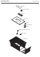
Place the LP gas tank upright into the tank tray and secure the tank by screw.
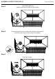
CONNECTING AND DISCONNECTING LP & NG
Before connecting, be sure that there is no debris
caught in the head of the LP gas tank, head of
the regulator valve or in the head of the burner
and burner ports.
Connect regulator/hose assembly to tank by
turning knob clockwise.
Before disconnecting make sure the LP gas tank valve
is "CLOSED."
Disconnect regulator/hose assembly from LP gas tank
by turning knob counterclockwise until it is loose.
Caution: LP gas tank must be properly disconnected
and removed prior to moving this pit.
1. A professionally-installed shut-o valve between the supply piping and the socket is
recommended, but not required, by the National Fuel Gas Code. Socket connection
must be made outdoors.
2. Coat the gas supply pipe nipple with gas-resistant pipe dope or approved teon tape. Screw socket onto gas
supply pipe (house gas source), and wrench-tighten.
3. Pull back the sleeve on the quick disconnect socket and insert the unattached end of the gas hose into the
socket. Release the sleeve and continue pushing the hose into the socket until the sleeve snaps into the
locked position.
4. When the quick disconnect socket and the gas hose are connected, a valve in the socket opens automatically
to permit full gas ow. When the gas hose is disconnected, the valve in the socket instantly and positively
shuts o the ow of gas, the grill can be disconnected from the gas source by disconnecting the gas hose
from the quick disconnect socket. The socket should be left attached to the gas source (hose piping).
With proper assembly, the gas hose cannot be removed without pushing the quick disconnect sleeve back. To
disconnect, push sleeve back and pull plug out of sleeve (this automatically shuts o gas). The appliance and its
individual shut o valve must be disconnected from the gas supply piping system during any pressure testing on
that system at test pressures in excess of 1/2 psi (3.5kPa).
The appliance must be isolated from the gas supply piping system by closing its individual manual shut o valve
during any pressure testing of the gas supply piping system at test pressures equal to or less than 1/2 psi (3.5kPa).
LP GAS
NG
Figure 236, Page 10