INSTALLATION INSTRUCTIONS 14 SEER Split System Air Conditioner & Heat Pump 1.5-5 Tons R410A NOTE: Appearance of unit may vary. RECOGNIZE THIS SYMBOL AS AN INDICATION OF IMPORTANT SAFETY INFORMATION WARNING These instructions are intended as an aid to qualified licensed service personnel for proper installation, adjustment and operation of this unit. Read these instructions thoroughly before attempting installation or operation.
TABLE OF CONTENTS 1. KEY TO SYMBOLS AND SAFETY INSTRUCTIONS............................................1 2. UNIT LOCATION CONSIDERATIONS.................................................................2 3. UNIT PREPARATION..........................................................................................3 4. SETTING UP THE UNIT.......................................................................................3 5. REFRIGERANT LINE CONSIDERATIONS.....................................................
All phases of this installation must comply with NATIONAL, STATE, AND LOCAL CODES. WARNING: HAZARDOUS VOLTAGE Failure to follow this warning could result in property damage, severe personal injury or death. 1. Key to symbols and safety instructions Disconnect all electric power, including remote disconnects before servicing. Follow proper lockout/tagout procedures to ensure the power cannot be inadvertently energized. 1.
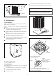
WARNING: HIGH CURRENT LEAKAGE Position unit where water, snow or ice from roof or overhang cannot fall directly on unit. Failure to follow this warning could result in property damage, severe personal injury or death. Grounding is essential before connecting electrical supply. Position the outdoor unit a minimum of 12’’ from any wall or surrounding shrubbery to ensure adequate airflow. See Figure 2 and Figure 3. 2. Unit location considerations Cold climate considerations (heat pump only) 2.
The pad must be high enough above grade to allow for drainage. The pad location must comply with National, State and Local codes. Min. 12" Snow barrier Snow legs These instructions are intended to provide a method to tie-down system to concrete slab as a securing procedure for high wind areas. Check Local Codes for tie-down methods and protocols. 3- 12" Elevation pad Figure 4 3. Unit preparation 3.
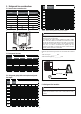
5. Refrigerant line considerations Model 5.1 Service valve connection sizes Model 18 Suction line Liquid line connection connection 24 30 18 3/4 3/8 24 3/4 3/8 30 3/4 3/8 36 3/4 3/8 42 3/4 3/8 48 7/8 3/8 60 7/8 3/8 36 42 48 60 Table 2 Suction line (Inches) 5/8 3/4 5/8 3/4 5/8 3/4 5/8 3/4 5/8 3/4 3/4 7/8 7/8 1-1/8 Total suction line length(Feet) 25 50 100 150 Coefficient 1.00 0.97 0.94 0.90 1.00 0.98 0.95 0.92 1.00 0.97 0.94 0.90 1.00 0.98 0.95 0.92 1.00 0.97 0.94 0.90 1.
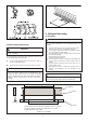
Figure 11 6. Refrigerant line routing 6.1 Precautions Figure 10 Take precautions to prevent noise within the building structure due to vibration transmission from the refrigerant lines. For example: 5.5 Reuse existing refrigerant lines When the refrigerant lines have to be fastened to floor joists or other framing in a structure, use isolation type hangers. Isolation hangers should also be used when refrigerant lines are run in stud spaces or enclosed ceilings.
Feet Maximum Wall Isolator 8 Feet Maximum Side View Line Set Secure Suc tion Line using isolators every 8 feet . Secure Liqu id Line directly to Suc tion Line using tape, wire, or other approp riate method every 8 feet.
4. Wrap a wet rag around the valve body to avoid heat damage and continue the dry nitrogen purge (Figure 19). 7. Refrigerant line brazing 7.1 Braze the refrigerant lines Braze the refrigerant lines to the service valves. 1. Remove caps or plugs. Use a deburing tool to debur the pipe ends. Clean both internal and external surfaces of the tubing using an emery cloth.
1. Evacuate until the micron gauge reads no higher than 350 microns, then close off the valve to the vacuum pump. 8. Refrigerant line leak check 8.1 Check for leaks 1. Pressurize the refrigerant lines and evaporator coil to 150 PSIG using dry nitrogen. 0350 Microns 150 PSIG ON OFF Figure 23 2. Observe the micron gauge. Evacuation is complete if the micron gauge does not rise above 500 microns in one (1) minute.
. Electrical - low voltage Cap 5/16” Hex Wrench for Sucti on Service Valve 11.1 Low Voltage Maximum Wire Length Table 6 defines the maximum total length of low voltage wiring from the outdoor unit to the indoor unit and to the thermostat. 3/16” Hex Wrench for Liqu id Service Valve Unit S ide of Service Valve 24 Volts - Wire size Max. wire length 18 AWG 150 Ft. 16 AWG 225 Ft. 14 AWG 300 Ft. Roll ed Edge to Capti vate Stem Hex Headed Valve System Table 6 Service Port Figure 25 11.
Support 2H thermostat Support 3H thermostat W W2 B C W1 R B C Y R G OUTDOOR UNIT w1 w2 INDOOR UNIT R C Y B PURPLE C BLUE R YELLOW D * BLACK PURPLE BLUE B WHITE Y BLACK INDOOR UNIT C THERMOSTAT RED R G GREEN w1 w2 YELLOW C Y * BLACK R WHITE RED G BLACK THERMOSTAT GREEN G D OUTDOOR UNIT Control Wiring for H/P Systems Figure 28 Notes: “-----”The electric auxiliary heat connection(option). W:Electric auxiliary heat signal.
4. Wait one (1) hour before starting the unit if compressor crankcase heater is used and the outdoor ambient temperature is below 70 ºF. 60 MIN. Figure 34 5. Set system thermostat to ON. Figure 31 TUE Inside Set To Following Schedule EM HEAT OFF COOL 13. Start up DONE CANCEL 13.1 System start up 1. Ensure Sections 7, 8, 9, 10, 11 and 12 have been completed. Figure 35 2. Set System Thermostat to OFF. 14. System charge adjustment OFF DONE 14.
Sealed-System Repairs — Calculating total system charge. 1. Total Line Length (ft) = 2. Standard Line set (ft) = 3. (a) minus (b) = (c) 4. Refrigerant Multiplier = (d) 5. Refrigerant Adder (c*d) = 6. Factory Charge (nameplate) = (f) 7. Total System Charge (e+f) _ 2. Ensure Sections 7, 8, 9, 10,11,12 and 13 have been completed. (a) 15 3. Stabilize the system by operating for a minimum of 20 minutes.
REFRIGERANT CHARGING CHART FOR AC SYSTEM Suction Pressure at Large Service Valve(psig) Cooling Mode 55 165 161 157 153 149 145 141 137 133 129 125 121 117 113 109 105 Suction Pressure at Large Service Valve(psig) Cooling Mode 165 161 157 153 149 145 141 137 133 129 125 121 117 113 109 105 Suction Pressure at Large Service Valve(psig) Cooling Mode 165 161 157 153 149 145 141 137 133 129 125 121 117 113 109 105 Suction Pressure at Large Service Valve(psig) Cooling Mode 165 161 157 153 149 145 141
Cooling Mode 55 Suction Pressure at Large Service Valve(psig) 165 161 157 153 149 145 141 137 133 129 125 121 117 113 109 105 Suction Pressure at Large Service Valve(psig) Cooling Mode 165 161 157 153 149 145 141 137 133 129 125 121 117 113 109 105 Suction Pressure at Large Service Valve(psig) Cooling Mode 165 161 157 153 149 145 141 137 133 129 125 121 117 113 109 105 204 202 200 198 196 194 192 190 188 186 55 60 65 227 225 223 221 219 217 215 213 211 209 207 205 203 250 248 246 244 242 240
Suction Pressure at Large Service Valve(psig) Cooling Mode 165 161 157 153 149 145 141 137 133 129 125 121 117 113 109 105 Suction Pressure at Large Service Valve(psig) Cooling Mode 165 161 157 153 149 145 141 137 133 129 125 121 117 113 109 105 Suction Pressure at Large Service Valve(psig) Cooling Mode 165 161 157 153 149 145 141 137 133 129 125 121 117 113 109 105 Suction Pressure at Large Service Valve(psig) Cooling Mode 165 161 157 153 149 145 141 137 133 129 125 121 117 113 109 105 55 204
Suction Pressure at Large Service Valve(psig) Cooling Mode 165 161 157 153 149 145 141 137 133 129 125 121 117 113 109 105 Suction Pressure at Large Service Valve(psig) Cooling Mode 165 161 157 153 149 145 141 137 133 129 125 121 117 113 109 105 55 206 204 204 202 200 198 196 194 192 190 55 201 199 197 195 193 191 189 187 185 183 60 231 229 227 225 223 222 220 218 216 214 212 210 208 60 225 223 221 219 217 215 213 211 209 207 205 203 201 14SEER R410A HP Charge Chart 4 TON(Cooling mode) Outdoor
15. System operation and troubleshooting 15.5 Defrost mode (Heat pump only) 15.1 Compressor crankcase heater (CCH) (Heat pump only) Manual defrost mode When the switch SW3-1 is set to “ON”, the system turns to the defrost mode. The defrost mode exits by the logic of shut-down conditions of defrost mode. The crankcase heating start must meet two conditions: A. Outdoor temperature<37.4°F B.
15.6 Temperature sensor resistance table Temperature °F Resistance kΩ Temperature °F Resistance kΩ Temperature °F Resistance kΩ Temperature °F Resistance kΩ -4 106.73 37 29.87 78 10.00 119 3.69 -3 103.25 38 29.22 79 9.50 120 3.61 -2 99.89 39 28.19 80 9.26 121 3.53 -1 96.65 40 27.39 81 9.03 122 3.45 0 93.53 41 26.61 82 8.81 123 3.38 1 90.53 42 25.85 83 8.59 124 3.30 2 87.62 43 25.12 84 8.38 125 3.23 3 84.83 44 24.42 85 8.17 126 3.16 4 82.13 45 23.73 86 7.97 127 3.10 5 79.52 46 23.07 87 7.78 128 3.03 6 77.
15.8 Troubleshooting table EF. RD SO EF. D SEN GS N S OR E F . E C/H H P P . S S OR D . N EF EM T3 T P. SE OL D N T R EF. T EM T4 ST CO SOR D G RO EN KIN D E F L PC S LEA VE CTIVE VAL E CK DEF KING CHE COIL EA S L SOV SOV CTION W TRI FLO RES IR. .D. AIR EAT .C I H R E F R E S. PER N U S OPE CK ION STU T A T X V I R C U L OW FL EC R R . AIR S D . . AI BLE O.D RES. O ENSA D D OA N L NCO EVAP. GE NO R IVE RCHA E ESS E G EXC EF. OV CHAR . R P R NDE T COM .
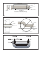
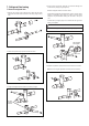
STEP 4 - Remove fan motor by removing 5/16” nuts from cover. STEP 5 - Remove fan blade from motor by removing 1/2” nut and place fan on the ground. Damage will occur to condenser unit if you remove 5/16’’ nuts prior to cover removal. STEP 6 - Reverse removal process to reinstall the fan and motor. Note: When connecting motor wires be sure to check motor direction. 1/2”nut 5/16”nuts Figure 43 17. Wiring diagrams 17.
17.
18. Matching table and Checkout Procedures 18.