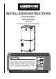
INSTALLATION INSTRUCTIONS HIGH EFFICIENCY AIR HANDLERS 1.5-5Tons FEATURING R410A OR R22 REFRIGERANT RECOGNIZE THIS SYMBOL AS AN INDICATION OF IMPORTANT SAFETY INFORMATION WARNING These instructions are intended as an aid to qualified licensed service personnel for proper installation, adjustment and operation of this unit. Read these instructions thoroughly before attempting installation or operation.
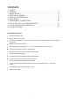
CONTENTS 1. SAFETY.................................................................................................................2 2. GENERAL...........................................................................................................3 3. APPLICATIONS..................................................................................................6 4. ELECTRICAL WIRING......................................................................................8 5. AIRFLOW PERFORMANCE...............
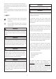
This document is customer property and is to remain with this unit. WARNING These instructions do not cover all the different variations systems nor does it provide for every possible contingency to be met in connection The unit must be permanently grounded. Failure to do so can with installation. result in electrical shock causing personal injury or death. All phases of this installation must comply with national state and local WARNING codes.
Do not install unit in an area where flammable materials are present CAUTION due to the risk of an explosion resulting in serious injury or death. WARNING Make sure the blower motor If the supporting structural members are not strong enough to take support is tight (3-motor mount the unit’s weight, the unit could fall out of place and cause serious bolts) then check to see if injury.
When the unit is installed in a hot and humid place, If the humidity inside the installation space might exceed 86℉ and RH 80%, it is recommended to insulate the cabinet exterior. Use glass wool or polyethylene foam as insulation so that the thickness is more than 2 in. and fits inside the installation space opening. Respectively, condensation may form on the surface of the insulation.
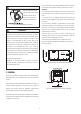
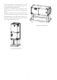
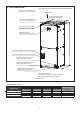
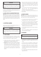
2.1 UNIT DIMENSIONS NOTE: 25” CLEARANCE IS REQUIRED IN THE FRONT OF THE UNIT FOR FILTER AND COIL MAINTENANCE.
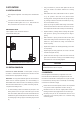
3 APPLICATIONS Using a screwdriver or pencil, lift white plastic tab with hole away from breaker until breaker releases from mounting 3.1 VERTICAL UPFLOW opening. With breaker held in hand, rotate breaker so that “on” position Vertical Upflow configuration is the factory set on all models.See is up, “off” position is down with unit in planned vertical Fig.6. mounting position.
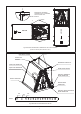
A 1:4 ENSURE THE RETAINING CHANNEL IS FULLY ENGAGED WITH THE COIL RAIL. DETAIL A RAILS AIRFLOW A AIRFLOW RAILS Fig.8 VERTICAL DOWNFLOW & HORIZONTAL LEFT APPLICATIONS (lower front service panel removed “view”.) STRAPS REAR WATER CATCHER TOP AIR STOP HORIZONTAL ADAPTER KIT VAPOR LINE CONNECTION LIQUID LINE CONNECTION FRONT WATER CATCHER AUXILIARY HORIZONTAL DRAIN CONNECTION VERTICAL DRAIN PAN PRIMARY DRAIN CONNECTION AUXILIARY UPFLOW/DOWNFLOW DRAIN CONNECTION 60K 36K 24K STRAPS Fig.
Supply circuit power wiring must be 75°C minimum copper CAUTION conductors only. See Electrical Data in this section for ampacity, Horizontal units must be configured for right hand air supply or left wire size and circuit protector requirement. Supply circuit hand air supply. Horizontal drain pan must be located under protective devices may be either fuses or “HACR” type circuit indoor coil. Failure to use the drain pan can result in property breakers. damage.
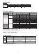
4.4 ELECTRICAL DATA MODEL 24 36 60 VOLTAGE HERTZ HP SPEEDS 208/230 208/230 208/230 60 60 60 1/3 1/2 3/4 5 5 5 CIRCUIT MAXIMUM CIRCUIT AMPS. PROTECTOR 2.6 15(A) 3.0 15(A) 4.5 15(A) 4.5 ELECTRIC KIT MCA/MOP DATA Heat Kit Air Handler Electric Model Model Heat(kW) MIN. Circuit Ampacity MAX.Fuse or Breaker (HACR) Ampacity Minimum Heating Blower Speed (AC/HP) 5 240 29.4 208 25.9 240 30 208 30 7.5 42.4 37.2 45 40 Low JAYHTR1A10BKR* 10 55.4 48.5 60 50 Low JAYHTR1A05BKR* 5 29.
5. AIRFLOW PERFORMANCE (OXBOX AIR HANDLERS ARE SUITABLE FOR MOBILE HOME APPLICATIONS) Airflow performance data is based on cooling performance with a coil and no filter in place. Select performance table for appropriate unit size. External static applied to unit allows operation within the minimum and maximum limits shown in table below for both cooling and electric heat operation. AIRFLOW PERFORMANCE DATA Air Handler Model Outdoor Unit Size(Tons) Motor Speed 1 2 (Recommended) 24 1.
Model Outdoor Unit Size(Tons) Motor Speed 1 2 (Recommended) 60 3.
6. DUCTWORK 7. REFRIGERANT CONNECTIONS Keep the coil connections sealed until refrigerant connections are Field ductwork must comply with the National Fire Protection made. See the Installation Instructions for the outdoor unit for details Association NFPA 90A, NFPA 90B and any applicable local on line sizing, tubing installation, and charging information. ordinance. Coil is shipped with Nitrogen. Evacuate the system before charging with refrigerant.
7.1 CONDENSATE DRAIN TUBING Auxiliary drain line should be run to a place where it will be noticeable if it becomes operational. Homeowner should be Consult local codes for specific requirements. warned that a problem exists if water should begin running from the auxiliary drain line. CONDENSATE DRAIN TRAP Plug the unused drain connection with the plugs provided in the parts bag, using a thin layer of teflon paste, silicone or teflon DO NOT OPERATE UNIT WITHOUT CONDENSATE DRAIN TRAP.
WARNING Do not operate the system without filters. A portion of the dust entrained in the air may temporarily lodge In the duct runs and at the supply registers. Any circulated dust particles could be heated and charred by contact with the air handler elements. This residue could soil ceilings, walls, drapes, carpets and other articles in the house. Soot damage may occur with filters in place, when certain types of candles, oil lamps or standing pilots are burned. 9.
Fig.13 AIR FILTER CLEAN 10.WIRING DIAGRAM 1. To avoid the electrical shock, please connect the air conditioner with the ground lug. The main power plug in the air conditioner has been joined with the ground wiring, please don't change it freely. 2. The power socket is used as the air conditioner specially. 3. Don't pull the power wiring hard. 4. When connecting the air conditioner with the ground, observe the local codes. 5.
HIGH VOLTAGE! DISCONNECT ALL POWER BEFORE SERVICING OR INSTALLING THIS UNIT. MULTIPLE POWER SOURCES MAY BE PRESENT. FAILURE TO DO SO MAY CAUSE PROPERTY DAMAGE, PERSONAL INJURY OR DEATH.
6 5 4 3 2 1 6 5 4 3 2 1 RED BLACK 0 WHITE W1 0 1 0 1 1 C 0 1 C BLUE BLACK BROWN WHITE BLACK BLACK/WHITE W2 WHITE BLACK most up-to-date wiring. 17 2 6 2 6 2 6 2 6 6 5 4 3 2 1 BLUE C Wiring is subject to change.
This coil comes with a factory installed piston metering device. See Table 1 for factory installed piston size. Some system combinations will require a different sized piston to be field installed. Contact your local parts center to order the appropriate MAYORIACHP piston kit for your system combination. Use Table 3 for TXV kit part numbers. A TXV may be required to achieve minimum efficiency ratings or for long refrigerant line set applications. Reference AHRI for system combination ratings.
NOTE: Since the manufacturer has a policy of continuous product and product data improvement, if the system combination you are looking for is not listed, check for the latest version of this document at www.OXBOXHVAC.com. Table 3 . Optional TXV kit part numbers. Some combinations may require a TXV. See AHRI for system combination ratings. Table 4.Superheat Charging Chart Charge the system by superheat when using a piston.