
J4AH4P Installation Manual


Auxiliary drain line should be run to a place where it will be
noticeable if it becomes operational. Homeowner should be
warned that a problem exists if water should begin running from
the auxiliary drain line.
Plug the unused drain connection with the plugs provided in the
parts bag, using a thin layer of teflon paste, silicone or teflon
tape to form a water tight seal.
Test condensate drain pan and drain line after installation is
complete. Pour water into drain pan, enough to fill drain trap and
line. Check to make sure drain pan is draining completely, no
leaks are found in drain line fittings, and water is draining from
the termination of the primary drain line.
Be sure to insulate the drain piping and drain socket since
condensation may cause water leakage.
Be sure to install a drain trap at the drain outlet since the inside
of the unit is at negative pressure relative to atmospheric
pressure during operation.
13
8. AIR FILTER (not factory-installed)
External filter or other means of filtration is required. Units should be
sized for a maximum of 300 feet/min air velocity or what is recomm-
ended for the type filter installed.
Filter application and placement are critical to airflow, which may affect
the heating and cooling system performance. Reduced airflow can
shorten the life of the system’s major components, such as motor,
limits, elements, heat relays, evaporator coil or compressor.
Consequently, we recommend that the return air duct system have
only one filter location. For systems with a return air filter grill or
multiple filter grills, can have a filter installed at each of the return air
openings.
If adding high efficiency filters or electronic air filtration systems, it is
very important that the air flow is not reduced. If air flow is reduced the
overall performance and efficiency of the unit will be reduced. It is
strongly recommended that a professional installation technician is
contacted to ensure installation of these such filtration systems are
installed correctly.
IMPORTANT: Do not double filter the return air duct system. Do not
filter the supply air duct system. This will change the performance of
the unit and reduce airflow .
7.1 CONDENSATE DRAIN TUBING
Consult local codes for specific requirements.
IMPORTANT:
1. When making drain fitting connections to the drain pan, use a thin
layer of Teflon paste, silicone or Teflon tape and install, hand tighten.
2. When making drain fitting connections to drain pan, do not
overtighten. Over tightening fittings can split pipe connections on the
drain pan.
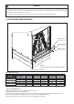
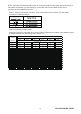
CONDENSATE DRAIN TRAP
DO NOT OVERTIGHTEN DRAIN FITTING
TOWARD DRAIN CONNECTION
UNIT MUST BE SLIGHTLY INCLINED
Fig.11 CONDENSATE DRAIN TRAP
3"
3"
UNIT
TO APPROVED DRAIN
Install drain lines so they do not block service access to front of
the unit. Minimum clearance of 24 inches is required for filter, coil
or blower removal and service access.
Make sure unit is level or pitched slightly toward primary drain
connection so that water will drain completely from the pan. (See
Fig.11)
Do not reduce drain line size less than connection size provided
on condensate drain pan. Use 3/4
"
PVC piping for drain piping
connections.
All drain lines must be pitched downward away from the unit a
minimum of 1/8
"
per foot of line to ensure proper drainage.
Do not connect condensate drain line to a closed or open sewer
pipe. Run condensate to an open drain or run line to a safe
outdoor area.
The drain line should be insulated where necessary to prevent
sweating and damage due to condensate forming on the outside
surface of the line.
Make provisions for disconnecting and cleaning of the primary
drain line should it become necessary. Install a 3 inch trap in the
primary drain line as close to the unit as possible. Make sure that
the top of the trap is below connection to the drain pan to allow
complete drainage of pan (See Fig. 11).
DO NOT OPERATE UNIT WITHOUT
CONDENSATE DRAIN TRAP.