
J4HP4 Installation Manual

2. Unit location considerations
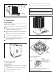
2.1 Unit dimensions
WARNING: HIGH CURRENT LEAKAGE
Failure to follow this warning could result in property damage,
severe personal injury or death. Grounding is essential before
connecting electrical supply.
2
Cold climate considerations (heat pump only)
Precautions must be taken for units being installed in areas where
snow accumulation and prolonged below-freezing temperatures
occur.
Table 1
The unit’s weight value is on the cardboard box.
When mounting the outdoor unit on a roof, be sure the roof will support
the unit’s weight. Properly selected isolation is recommended to prevent
sound or vibration transmission to the building structure.
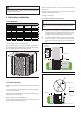
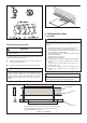
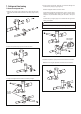
2.2 Location restrictions
Ensure the top discharge area is unrestricted for at least 60 inches above
the unit.
Do not locate outdoor unit near bedrooms since normal operational
sounds may be objectionable.
Position unit to allow adequate space for unobstructed airflow, wiring,
refrigerant lines, and serviceability.
Maintain a distance of 24 inches between units.
24 inches clearance must be provided in front of the control box (access
panels) and any other side requiring service.
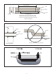
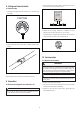
Units should be elevated 3-12 inches above the pad or rooftop,
depending on local weather. This additional height will allow
drainage of snow and ice melted during defrost cycle prior to its
refreezing. Ensure that drain holes in unit base pan are not
obstructed, preventing drainage of defrost water (Figure 4).
If possible, avoid locations that are likely to accumulate snow
drifts. If not possible, a snow drift barrier should be installed
around the unit to prevent a build-up of snow on the sides of the
unit.
Min. 12’’ to
Shrubbery
Avoid Install
Near Bedrooms
Min. 60” Unrestricted
Access Panel
Min. 24’’
Unrestricted
Figure 2
Figure 1
Min. 12” to
Shrubbery
Min. 12” to
Wall
Figure 3
Position unit where water, snow or ice from roof or overhang cannot fall
directly on unit.
Position the outdoor unit a minimum of 12’’ from any wall or surrounding
shrubbery to ensure adequate airflow.
See Figure 2 and Figure 3.
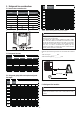
AC HP
18 24-15/16 21-7/8 21-7/8
24 18/24 24-15/16 23-5/8 23-5/8
30 30 24-15/16 28 28
36 36 24-15/16 29-1/8 29-1/8
4242 33-3/16 28 28
48 48 33-3/16 28 28
60 60 33-3/16 29-1/8 29-1/8
Unit Dimensions
Model
H(Inches) W(Inches) L(Inches)
/