
J4HP4 Installation Manual
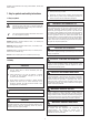
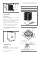

3. Unit preparation
3
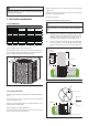
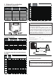
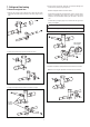
These instructions are intended to provide a method to tie-down
system to concrete slab as a securing procedure for high wind
areas. Check Local Codes for tie-down methods and protocols.
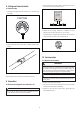
Min. 12"
Snow
barrier
3- 12" Elevation
Snow legs
pad
Figure 4
3.1 Pre-installation
4. Setting up the unit
4.1 Pad installation
STEP 1 - Check for damage and report promptly to the carrier any
damage found to the unit (Figure 5).
STEP 2 - Instruments must be designed to install/serve R410A
equipmens.
Gauge sets, hoses, refrigerant containers and recovery system
must be designed to handle the POE type oils.
Manifold sets should be 800 PSIG high side and 250 PSIG low
side.
All hoses must have a 700 PSIG service pressure rating.
Leak detectors should be disigned to detect R410A.
Recovery equipments (including refrigerant recovery containers
) must be specifically designed to handle R410A.
Do not use an R22 TXV.
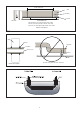
The pad must be at least 1-2” larger than the unit on all sides.
The pad must be separate from any structure.
The pad must be level.
Figure
5
When installing the unit on a support pad, such as a concrete slab,
consider the following:
Figure
6
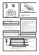
#7 X 3/8” Self Tapping Screws
(Don’t Exceed 3/8” long)
Detail A
The dimension
see Unit Dimensions.
See Detail A
Brackets:
2" width, 1/16" thickness,
height as required.
Available from distributor
or in market place.
1/4” Χ 1-1/2” Hex Washer Head Concrete Screws
(3/16” Pilot Hole Needed. Pilot Hole Should Be 1/4” Deeper
Than The Fastener Embedment)
Figure
7
The pad must be high enough above grade to allow for drainage.
The pad location must comply with National, State and Local codes.