INSTALLATION INSTRUCTIONS PACKAGE HEAT PUMP & AIR CONDITIONER FEATURING R-410A 14 SEER J4PH4 SERIES - (2-5Tons) RECOGNIZE THIS SYMBOL AS AN INDICATION OF IMPORTANT SAFETY INFORMATION WARNING These instructions are intended as an aid to qualified, licensed service personnel for proper installation, adjustment and operation of this unit. Read these instructions thoroughly before attempting installation or operation.
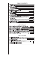
TABLE OF CONTENTS LIST OF TABLES LIST OF FIGURES
This document is customer property and is to remain with this unit. These instructions do not cover all the different variations of systems nor does it provide for every possible contingency to be met in connection with installation. All phases of this installation must comply with NATIONAL, STATE and LOCAL CODES. If additional information is required please contact your local distributor. 1.
WARNING The unit must be permanently grounded. A grounding lug is provided. Failure to ground this unit can result in fire or electrical shock causing property damage, severe personal injury or death. WARNING Only electric heater kits supplied by this manufacturer as described in this publication have been designed, tested, and evaluated by a nationally recognized safety testing agency for use with this unit.
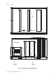
2.2 CLEARANCE All units require certain clearance for proper operation and service. Refer to Table 2-1 for the clearances required for construction, servicing and proper unit operation. 2.3 RIGGING AND HANDING Exercise care when moving the unit. Do not remove any packaging until the unit is near the place of installation. Rig the unit by attaching chain or cable slings to the lifting holes provided in the base rails.
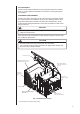
Unit size:024, 030, 036 Front 24-13/16″ 2-3/8″ 8-9 /16 ″ 6- 5/8 ″ 18 -1 /2″ /8″ 6-5 3-11/16″ 3″ 21 -9 52 /16″ ″ 3″ 4-5 Hi./Lo. pressure service port 1/4’’ SAE 65/8 ″ Condensate drain connection 3/4” NPTI (Trap required) /16 12 6-5 ″ 1-9 /1 6″ 5- 7 /8″ /8 ″ /1 -11 6″ 4″ -3/ 37 Low voltage entrance 7/8” Dia. High voltage conn. 1-3/8” Dia. Electrical service access compapartment panel Fig. 2-2 Unit Dimensions * The above figure for reference purpose only.
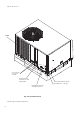
Unit size:024, 030, 036 35-15/16″ 1-13/16″ Bottom View 1-3/4″ 1-13/16″ 50-1/4″ 1-3/4″ 4-1/4″ 14-1/2″ 18″ Back View 1-5/8″ 14-1/2″ Side supply air opening 4-3/8″ 14-1/2″ Side return air opeing Fig. 2-3 Dimensions Back and Bottom * The above figure for reference purpose only.
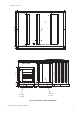
Unit size:042, 048, 060 Front 33-1/16″ 2-3/8″ 10 -3 /8″ 6- 5/8 ″ 22 /2″ 24 ″ 58 -1 /2 ″ 4-7 /16 ″ Condensate drain connection 3/4” NPTI (Trap required) /8″ 6-5 ″ 1-9 /16 ″ 8-1 -1 42 ″ /16 ″ ″ /16 Low voltage entrance 7/8” Dia. Electrical service access compapartment panel Fig. 2-4 Unit Dimensions 8 / 16 -11 12 3″ 5/8 * The above figure for reference purpose only. 6-5 3″ 6- Hi./Lo. pressure service port 1/4’’ SAE /8″ 3-11/16″ -1 High voltage conn. 1-3/8” Dia.
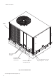
Unit size:042, 048, 060 40-1/4″ 1-13/16″ Bottom View 1-3/4″ 1-13/16″ 56-3/4″ 1-3/4″ 4-1/4″ 14-1/2″ 24″ Back View 2-1/4″ 6-5/16″ 14-1/2″ 14-1/2″ Side return air opeing Side supply air opening Fig. 2-5 Dimensions Back and Bottom * The above figure for reference purpose only.
Table 2-1: Unit Clearance D ir e c tio n D i s t a n c e ( i n .) D ir e c tio n D i s t a n c e ( i n .) To p 6 0 Ri g h t 12 F ro n t 3 0 Le f t 24 Re a r 18 1 2 B o tto m 3 0 D uct clearance: 1 inch clearance for all sides of air supply duct. 1. Units must be installed outdoors. Over hanging structure or shrubs should not obscure condenser air discharge outlet. 2. The minimum clearance without economizer/fresh air damper.
3.0 DUCTWORK Ductwork should be sized and installed by the installing contractor in accordance with the Manual D from the Air Conditioning Contractors of America, and all national, state and local codes. NOTE On ductwork exposed to outside air space, use at least 2” of insulation and a vapor barrier. Flexible joint may be used to reduce noise. A closed return duct system shall be used. This shall not preclude use of economizers or ventilation air intake.
5.0 FILTERS Units are shipped without a filter or filter racks. It is the responsibility of the installer to secure a filter in the return air ductwork or install a filter/frame Kit. Filter must always be used and must be kept clean. Dirty filters may cause insufficient air delivery, decreasing unit efficiency and increasing operation costs and wear-and tear on the unit and controls. Filters should be checked monthly; this is especially important since this unit is used for both heating and cooling. 6.
6.2 GROUNDING WARNING The unit must be permanently grounded. Failure to do so can result in electrical shock causing personal injury or death. • The unit must be electrically grounded in accordance with local codes or the national electric code. • Grounding may be accomplished by attaching ground wire(s) to ground lug(s) provided in the unit wiring compartment. 6.
UNIT CONTROL BOARD TERMINAL STRIP ** R R G G Y Y * W W1 240V 208V 24 volt transformer THERMOSTAT W2 *** B C COM B C Fig. 6-1 Typical Field Control Wiring Diagram *** B wire be used with heat pump system only, reversing valve energizes at the heating mode, and cut off at the cooling mode. ** Minimum wire size of 18 AWG wire should be used for all field installed 24 volt wire. * Only required on units with supplemental electric heat.
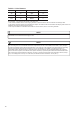
12. 0A 13. 0A 15. 2A 17. 3A 21. 5A 208/ 230-1-60 208/ 230-1-60 2 08/ 230-1-60 208/ 230-1-60 208/ 230-1-60 J4PH4030A1000AA J4PH4036A1000AA J4PH4042A1000AA J4PH4048A1000AA J4PH4060A1000AA 024/030: Rotary compressor 036/042/048/060: Scroll compressor 8. 45A 2 08/ 230-1-60 J4PH4024A1000AA R LA Volt U nit Model 125A 108A 112. 3A 34. 3A 28. 5A 24. 8A 22. 9A 21. 7A 59. 93A 75A 14. 87A MC C 34. 8A LR A C om pres s ors (eac h) Table 6-1: Electric Heat Circuit Ratings 6.
Table 6-2: 14 SEER Physical Data Models Component J4PH4024A1000AA J4PH4030A1000AA J4PH4036A1000AA J4PH4042A1000AA J4PH4048A1000AA J4PH4060A1000AA Nominal Tonnage 2.0 2.5 3.0 3.5 4.0 5.0 ARI COOLING PERFORMANCE Gross Capacity @ ARI A point (Btu) 23,717 30,921 35,770 42,070 48,411 58,911 ARI net capacity (Btu) 22,800 30,000 34,200 40,500 46,500 57,000 EER 11 11 11 11.5 11.5 SEER 14 14 14 14 14 14 1400 1600 2000 Nominal CFM 850 1050 1220 System power (kW ) 2.0 2.
7.0 AIRFLOW PERFORMANCE Airflow performance data is based on cooling performance with a coil and no filter in place. Use this performance table for appropriate unit size, external static applied to unit and allow operation within the minimum and maximum limits shown in table below for both cooling and electric heat operation. 7.
Table 7-1 Duct Application(208v) (Continued) Model Number Motor Speed Low 60 Middle High CFM(L/S) RPM Watts Amps CFM(L/S) RPM Watts Amps CFM(L/S) RPM Watts Amps 0[0] 1865(879) 851 641 3.08 0.1[.02] 1822(859) 886 620 2.98 CFM(L/S)(Watts) External Static Pressure-Inches W.C.[kPa] 0.2[.05] 0.3[.07] 0.4[.10] 0.5[.12] 1770(835) 1712(808) 1643(775) 919 948 974 598 578 555 2.88 2.79 2.69 1875(884) 1808(853) 1729(816) 1642(774) 961 984 1005 1024 664 639 613 587 3.21 3.11 3.0 2.
* The above airflow data for reference only. * In any stituation , the airflow of the unit should be in the range of 80% to 130% of 400CFM/Ton. ● The air distribution system has the greatest effect on airflow. The duct system is totally controlled by the contractor. For this reason, the contractor should use only industry-recognized procedures. ● Heat pump systems require a specified airflow. Each ton of cooling requires between 350 and 450 cubic feet of air per minute (CFM), or 400 CFM nominally.
Table 7-3 Refrigerant charge for H/P system Vanne Détectée de Pression Basse(en psig) Low Pressure Service Port(psig) 24 Cooling Mode Mode De Refroidissement 165 161 157 153 149 145 141 137 133 129 125 121 117 113 109 105 Cool ing Charge Chart/Tableau De Charge de Refroidissement O u t d o o r A m b i e n t T e m p e r a t u r e ( oF ) / T e m p e r a t u r e A m d i a n t e E x t e r i e u r e ( e n o F ) 55 256 251 246 241 236 231 226 221 216 211 60 282 279 275 272 268 264 260 256 252 248 244 240 2
Table 7-6 Refrigerant charge for H/P system Vanne Détectée de Pression Basse(en psig) Low Pressure Service Port(psig) 30 Heating Mode Mode De Chauffage Heating Charge Chart/Tableau De Charge de Chauffage I n d o o r D r y B u l b T e m p e r a t u r e ( oF ) / T e m p e r a t u r e I n t e r i e u r a u T h e m o m e t r e s e c ( e n o F ) 60 62 64 66 68 70 72 74 76 78 80 82 High Pressure Service Port(psig)/Vanne Détecté de Pression Haute(en psig) 135 128 121 114 107 100 93 86 79 72 65 58 5
Table 7-9 Refrigerant charge for H/P system 42 Cooling Mode Mode De Refroidissement 165 161 157 153 149 145 141 137 133 129 125 121 117 113 109 105 Low Pressure Service Port(psig) Vanne Détectée de Pression Basse(en psig) 55 60 240 238 236 234 232 230 228 226 224 222 220 218 216 212 210 208 206 204 202 200 198 196 194 Cooling Charge Chart/Tableau De Charge de Refroidissement Outdoor Ambient Temperature(oF)/Temperature Amdiante Exterieure(en oF) 65 70 75 80 85 90 95 100 105 High Pressure Service Port(
48 Heating Mode Mode De Chauffage 135 128 121 114 107 100 93 86 79 72 65 58 51 44 37 30 Vanne Détectée de Pression Basse(en psig) Low Pressure Service Port(psig) Table 7-12 Refrigerant charge for H/P system 60 62 418 392 366 340 314 288 279 269 260 250 241 426 400 374 347 321 295 285 276 266 257 247 Heating Charge Chart/Tableau De Charge de Chauffage Indoor Dry Bulb Temperature(oF)/Temperature Interieur au Themometre sec(en oF) 64 66 68 70 72 74 76 78 80 High Pressure Service Port(psig)/Vanne Détecté
8.0 SYSTEM OPERATION 8.1 COMPRESSOR CRANKCASE HEATER(OPTIONAL) Refrigerant migration during the off cycle can result in a noisy start up. Add a crankcase heater to minimize refrigeration migration, and to help eliminate any start up noise or bearing “wash out”. All heaters are located on the lower half of the compressor shell. Its purpose is to drive refrigerant from the compressor shell during long off cycles, thus preventing damage to the compressor during start-up.
Low pressure protection When low pressure is <21PSIG,the compressor and the outdoor fan motor will stop running. When low pressure is >44PSIG,the compressor and the outdoor fan motor will resume running(3 minutes delay necessary ). In stand-by status, if low pressure protection was detected, the compressor will not start. If protection cycles occur four times within 30 minutes, the compressor and outdoor fan will shut down.
Shut-down conditions of defrost mode: No matter what defrost mode is selected, the defrost cycle will end in any of the following conditions: 1. The defrost cycle has been running for 10 minutes; 2. T3 is ≥ 77 °F and T4 ≥ 28.4 °F; 3. The compressor stops operating; 4. T3 is ≥ 77 °F for more than 60s when T4 < 28.4 °F. 8.4 THERMOSTAT SIGNALS Table 8-1: Thermostat Signals Signal State Board Function G ON OFF Blower instant ON G & W1 Blower 90 sec. delay OFF ON Blower instant ON Heater bank 1 elec.
9.0 OPERATION CHECK-UP • Cooling Startup 1. Turn thermostat to OFF and turn power to ON 2. Turn ON thermostat and set as high as possible 3. Turn Fan switch ON and indoor blower should run 4. Turn fan switch to AUTO, system switch to COOL and thermostat tem perature setting below room temperature. Unit should run in COOLING mode. • Heating Startup After normal cooling run 1. Turn thermostat switch to HEAT. After unit stops, wait about 5 minutes. 2. Turn thermostat setting above room temperature.
OFF 1 2 3 ON SW3-1 OFF SW3-2 ON RESERVED OFF SW3-3 ON OFF IFM BLUE(L) RED(M) CC RED T4 T3 M1 SW3 DFC LED1 HEAT W2 B Y G W1 C R C RV RV MANUAL DEFROST INFAN M2 CN20 CN23 O_FAN C Y-OUT CN17 PLUG PLATE WHITE/BLACK BLUE YELLOW GREEN WHITE CCH GROUND L2 L1 6 5 4 3 2 1 HEATER KIT PLUG TO THERMOSTAT NOTES: 1: Remove the red lead from 240V terminal and then connect the red lead to 208V terminal on the transformer for 208 volts.
OFF 1 2 3 IFM 4 3 RED T4 T3 SW3 DFC LED1 W2 B Y G W1 C R C RV RV MANUAL DEFROST C D/W1 CN20 CN23 O_FAN C Y-OUT CN17 HEAT 208V terminal on the transformer for 208 volts. WHITE CC NOTES: 1: Remove the red lead from 240V terminal and then connect the red lead to 2: W2 wire is not provided in some models.
OFF ON IFM 5 4 RED T4 T3 SW3 DFC LED1 W2 B Y G W1 C R C RV RV MANUAL DEFROST C D/W1 CN20 CN23 O_FAN C Y-OUT CN17 PLUG PLATE HEAT 208V terminal on the transformer for 208 volts. WHITE CC NOTES: 1: Remove the red lead from 240V terminal and then connect the red lead to 2: W2 wire is not provided in some models.