
J801X Installation Manual


30
Blo
wer Door Switch
Burner Assemb
ly
Flame Sensor
Gas Manifold
Gas Valve
Igniter
Inducer
Assembly
Pressure Switch
Roll-Out Switch
Transformer
Blower
Assembly
Control Board
Main Air
Limit Switch
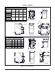
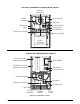
UPFLOW / HORIZONTAL FURNACE (Model J801X*U)
Figure 21. Component Locations
Combustion Tube
Gas Manifold
Gas Valve
Inducer Assembly
Control Board
Pressure Switch
Transformer
Blower Assembly
(behind
blower panel)
Burner
Assembly
Flame
Sensor
Roll-Out
Switch
Igniter
Main Air Limit Switch
Blower Door Switch
(behind
blower panel)
DOWNFLOW FURNACE (Model J801X*D)