SINGLE STAGE HIGH EFFICIENCY GAS FURNACES 80+ AFUE INSTALLATION INSTRUCTIONS J801X*U UPFLOW / HORIZONTAL FURNACE J801X*D DOWNFLOW FURNACE WARNING FIRE OR EXPLOSION HAZARD • Failure to follow safety warnings exactly could result in serious injury, death or property damage. • Installation and service must be performed by a qualified installer, service agency or the gas supplier. • Do not store or use gasoline or other flammable vapors and liquids in the vicinity of this or any other appliance.
TABLE OF CONTENTS IMPORTANT SAFETY INFORMATION..........................3 REQUIREMENTS & CODES..........................................3 Combustion Air Quality...............................................4 Clearances to Combustible Materials.........................4 Heating Load..............................................................4 Installation in a Garage...............................................5 Operation of Furnace During Construction.................
IMPORTANT SAFETY INFORMATION INSTALLER: Please read all instructions before servicing this equipment. Pay attention to all safety warnings and any other special notes highlighted in the manual. Safety markings are used frequently throughout this manual to designate a degree or level of seriousness and should not be ignored. WARNING - indicates a potentially hazardous situation that if not avoided, could result in personal injury or death.
The information listed below is for reference purposes only and does not necessarily have jurisdiction over local or state codes. Always consult with local authorities before installing any gas appliance.
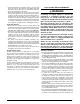
COMBUSTION AIR & VENTING REQUIREMENTS CLEARANCES TO COMBUSTIBLE MATERIALS* UPFLOW & DOWNFLOW APPLICATIONS WARNING: FRONT FRONT BOTTOM SIDE TOP RIGHT SIDE TOP HORIZONTAL APPLICATIONS VENT VENT LEFT SIDE BACK SIDE Left Side.................. 0 Inches Top...........................1 Inch Right Side................ 0 Inches Front......................... †4 Inches Vent......................... 6 Inches Back........................ 0 Inches Allow 24 in. minimum clearance for servicing.
IMPORTANT INFORMATION: • Provisions must be made during the installation of this furnace that provide an adequate supply of air for combustion. Furnace installation using methods other than those described in the following sections must comply with the National Fuel Gas Code (NFGC) and all applicable local codes. • Instructions for determining the adequacy of combustion air for an installation can be found in the current revision of the NFGC (ANSI Z223.1 / NFPA54).
Ventilation louvers at each end of attic Water Heater Furnace Inlet air duct must be at least 1 sq. in. per 4,000 Btuh of total input rating. Crawl Space 12" Max --- NOTE: Each opening to outside must be at least 1 sq. in. per 2,000 Btuh of total input rating.
Alternate Method of Providing Air from Outside: If acceptable under local Codes, it is permitted to provide outside air using one opening (See NFGC). Generally, confined spaces must have 2 openings in the space for combustion air. One opening must be within 12 inches of the ceiling, and the other must be within 12 inches of the floor. However, an alternative method recently adopted by the NFGC uses one opening within 12 inches of the top of the space.
• Sheet metal fasteners should be used to secure the vent pipe to the furnace flue. However, the NFGC states that alternative vent products may be attached according to the vent manufacturers instructions. • When an existing furnace is removed from a vent system serving other appliances, the existing vent system may no longer be sized to properly vent the remaining appliances. An improperly sized venting system can result in the formation of condensate, leakage, or spillage.
manually operated damper is installed, it must be designed so that operation of the furnace is prevented when the damper is in the cooling position and operation of the cooling system is prevented when the damper is in the heating position. • Seal all connections and joints with industrial grade sealing tape or liquid sealant. Requirements for sealing ductwork vary from region to region. Consult with local codes for requirements specific to your area.
FURNACE INSTALLATION These Installation procedures are suggested for typical furnace installations. Since each installation is different, the sequence of instructions may differ from the actual installation. Only qualified HVAC technicians should install this furnace. The installer must be familiar with and comply with all codes and regulations applicable to the installation of these heating appliances and related equipment.
threaded rod. Fasten the frame together with nuts, washers, and lockwashers. Secure the support frame to the rafters with lag bolts. The furnace can also be suspended using steel straps around each end of the furnace. The straps should be attached to the furnace with sheet metal screws and to the rafters with bolts.
Alternate Bottom Panel Removal Pressure Switch Tubing Figure 10 displays the proper routing of pressure switch tubing for J801X*U & J801X*D furnaces. On both furnaces, the tubing connects at one end of the pressure switch and is routed directly onto the static tap of the inducer assembly. If the bottom panel cannot be removed using the previous instructions, the steps below are an alternate method for removing the bottom panel. See Figure 12. 1. Remove the door from the blower compartment . 2.
GAS SUPPLY & PIPING WARNING: FIRE OR EXPLOSION HAZARD • Failure to follow safety warnings exactly could result in serious injury, death or property damage. • Installation and service must be performed by a qualified installer, service agency or the gas supplier. • Do not store or use gasoline or other flammable vapors and liquids in the vicinity of this or any other appliance. WHAT TO DO IF YOU SMELL GAS • Do not try to light any appliance.
UPFLOW MODELS 1 1 9 6 3 8 5 2 7 4 1 180 120 90 60 BLOWER OFF DELAY 180 120 90 60 See Note Shut - Off Valve NEUTRALS LOW ML MH HIGH EAC L1 XFMR HUM LOW ML MH HIGH EAC L1 XFMR HUM NEUTRALS L1A 6 3 5 2 4 1 Dripleg HEAT COOL FAN BLOWER OFF DELAY STATUS FLAME L1A Shut - Off Valve FLAME 24V HEAT COOL FAN 9 6 3 8 5 2 7 4 1 6 3 5 2 4 1 R C Y G W STATUS 24V R C Y G W See Note Dripleg Plug Manifold Ground Joint Union Manifold Ground Joint Union Burner Assembly Left Side Entry Right
The furnaces are shipped from the factory with orifices and gas regulator settings for natural gas operation at sea level altitudes. At 2,000 feet, the NFGC requires that this appliance be derated 4% for each 1,000 feet of altitude. For example, at 2,000 feet the input needs to be reduced 8%, at 3,000 feet (12%), etc. This deration is in reference to the input rate and gas heating value at sea level. To derate the furnace requires knowing the heating value of the gas at the installation site.
ELECTRICAL WIRING Thermostat / Low Voltage Connections • Electrical connections must be in compliance with all applicable local codes and the current revision of the National Electric Code (ANSI/NFPA 70). • For Canadian installations the electrical connections and grounding shall comply with the current Canadian Electrical Code (CSA C22.1 and/or local codes). • The furnace is designed to be controlled by a 24 VAC thermostat.
FURNACE INPUT (BTUh) FURNACE MODEL CABINET WIDTH (IN.) NOMINAL ELECTRICAL SUPPLY MAXIMUM OPERATING VOLTAGE MINIMUM OPERATING VOLTAGE MAXIMUM FURNACE AMPERES MAXIMUM FUSE OR CIRCUIT BREAKER AMPS* J801X045AU 45,000 14 1/4 115-60-1 127 103 6.8 15 J801X054AU 52,000 14 1/4 115-60-1 127 103 6.8 15 J801X072BU 70,000 17 1/2 115-60-1 127 103 9.2 15 J801X072CU 75,000 21 115-60-1 127 103 9.2 15 J801X090BU 90,000 17 1/2 115-60-1 127 103 9.
One stage heating • Connect the thermostat wires to the primary furnace control board. Mount the relay on the bracket on the secondary furnace. • Connect W from the primary furnace to the coil side of the relay (using field supplied wire and 3/16” terminals). • Connect C from the primary furnace to the coil side of the relay (using field supplied wire and 3/16” terminals). NOTE: Make sure connections are made on opposite sides of the coil.
EXAMPLE • Time for 1 revolution of a gas meter with a 1 cubic ft dial = 40 seconds. • From Table 5 read 90 cubic ft gas per hr. • Local heating value of the gas (obtained from gas supplier) = 1,040 Btu per cubic ft. • Input rate = 1,040 x 90 = 93,600 Btuh. WARNING: Do not attempt to drill the gas orifices. Use only factory supplied orifices. Improperly drilled orifices may cause fire, explosion, carbon monoxide poisoning, personal injury or death. 6.
OPERATING SEQUENCE The operating sequences for the heating, cooling, and fan modes are described below. Refer to the field and furnace wiring diagrams:Figure 14, (page 18), Figure 15, (page 18) and Figure 19, (page 24) and Figure 20, (page 25). Heating Cycle 1. The thermostat calls for heat by energizing the W terminal with 24VAC. 2. The control verifies the pressure switch is open. 3. If the pressure switch is open, the control energizes the inducer and waits for the pressure switch to close.
may have accumulated in the compartment or on the blower and motor as part of the annual inspection. Cleaning of Burners - If the burners must be cleaned, follow steps 1 - 12. See Figure 21, (page 30) for component location. 1. Shut off gas supply to the furnace at the meter or at a manual valve in the supply piping. 2. Turn off all power to the furnace and set the thermostat to its lowest setting. 3. Remove the burner door from the furnace. 4. Turn the gas control switch to the OFF position. 5.
FIGURES & TABLES J801X*U 80+ UPFLOW FURNACE J801X045AU J801X054AU J801X072BU J801X090BU DIM. -A- DIM. -B- DIM. -C- DIM. -D- 14 1/4 10 3/4 12 5/8 12 7/8 TOP VIEW C Front Brace FL 23 17 1/2 11 3/4 15 7/8 16 1/8 21 14 19 3/8 19 5/8 24 1/2 15 1/4 22 7/8 23 1/8 BOTTOM VIEW D AN 19 GE S Bottom Panel 23 1/2 MODEL # J801X072CU B J801X108CU Accepts 4” Type B Vent Pipe T-stat (Ø 7/8) NOTE: Dimensions shown in Inches.
Figure 19.
LADDER DIAGRAM Single Stage Furnaces L1 GND DOOR SWITCH N NEUTRAL GND L1 FLAME SENSOR GND P1-7 K4 EAC K3 P2-3 NEUTRAL BLOWER MOTOR CHOKE (SOME MODELS) NEUTRAL ELECTRONIC AIR CLEANER P2-6 HOT SURFACE IGNITOR HUM K2 NEUTRAL HUMIDIFIER P2-1 P2-4 INDUCER NEUTRAL XFORMER 120 VAC See Note TRANSFORMER R 3A FUSE W 24 VAC 24V TO MOTOR RELAYS P1-8 G SUPPLY AIR ROLL-OUT LIMIT LIMIT P1-3 P1-6 MICRO Y P1-5 K1 PRESSURE SWITCH BLOWER LIMIT SWITCH BLOWER DECK LIMIT SWITCH See Note
Gas Information GAS FLOW RATES (CUBIC FEET PER HOUR) TIME FOR ONE REVOLUTION (SECONDS) GAS FLOW RATES (CUBIC FEET PER HOUR) CUBIC FEET PER REVOLUTION OF GAS METER CUBIC FEET PER REVOLUTION OF GAS METER 1 5 10 TIME FOR ONE REVOLUTION (SECONDS) 1 5 10 10 12 360 300 1,800 1,500 3,600 3,000 66 68 55 53 273 265 545 529 14 257 1,286 2,571 70 51 257 514 16 225 1,125 2,250 72 50 250 500 18 200 1,000 2,000 74 49 243 486 20 180 900 1,800 76 47 237 474 22 164 818 1
PROPANE DERATION CHART ALTITUDE ABOVE SEA LEVEL 0 to 1,999 FT 2,000 to 2,999 FT 3,000 to 4,999 FT 5,000 to 5,999 FT 6,000 to 7,999 FT 8,000 to 10,000 FT INPUT (BTUh) 45,000 52,000 54,000 70,000 85,000 90,000 108,000 122,000 57 56 56 56 56 56 56 56 10.0 10.0 10.0 10.0 10.0 10.0 10.0 10.0 ORIFICE SIZE 57 56 56 56 56 56 56 56 9.0 9.0 9.0 9.0 9.0 9.0 9.0 9.0 MANIFOLD PRESSURE 57 56 56 56 56 56 56 56 ORIFICE SIZE 8.5 8.5 8.5 8.5 8.5 8.5 8.5 8.
NATURAL GAS W/ HIGH HEATING VALUE ALTITUDE ABOVE SEA LEVEL 0 to 1,999 FT 2,000 to 2,999 FT 3,000 to 3,999 FT 4,000 to 4,999 FT 5,000 to 5,999 FT 6,000 to 6,999 FT 7,000 to 7,999 FT 8,000 to 8,999 FT 9,000 to 9,999 FT INPUT (BTUh) 45,000 52,000 54,000 70,000 85,000 90,000 108,000 49 47 47 47 47 47 47 122,000 47 ORIFICE SIZE 3.5 3.5 3.5 3.5 3.5 3.5 3.5 3.5 MANIFOLD PRESSURE 49 47 47 47 47 47 47 47 ORIFICE SIZE 2.9 3.2 3.2 3.2 3.2 3.2 3.2 3.
TROUBLESHOOTING FURNACE COMPONENTS If the furnace fails to operate check the following: • Is the thermostat operating properly? • Are the blower compartment door(s) in place? • Is the furnace disconnect closed? • Has the circuit breaker tripped or the control board fuse burned open? • Is the gas turned on? • Are any manual reset switches open? • Is the filter dirty or plugged? • Is the flame sensor coated? (Remove and clean with steel wool).
UPFLOW / HORIZONTAL FURNACE (Model J801X*U) Main Air Limit Switch Inducer Assembly Control Board Gas Valve Pressure Switch Transformer Flame Sensor Gas Manifold Igniter Blower Door Switch Burner Assembly Roll-Out Switch Blower Assembly DOWNFLOW FURNACE (Model J801X*D) Combustion Tube Blower Assembly (behind blower panel) Blower Door Switch (behind blower panel) Control Board Transformer Pressure Switch Inducer Assembly Gas Valve Main Air Limit Switch Gas Manifold Igniter Burner Assembly Roll-
INSTALLATION CHECKLIST ELECTRICAL SYSTEM INSTALLER NAME: CITY: STATE: INSTALLATION ADDRESS: CITY: Electrical connections tight? YES NO Line voltage polarity correct? YES NO Supply Voltage:................................................................