
J801X Installation Manual

20
EXAMPLE
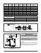
• Time for 1 revolution of a gas meter with a 1 cubic ft
dial = 40 seconds.
• From Table 5 read 90 cubic ft gas per hr.
• Local heating value of the gas (obtained from gas
supplier) = 1,040 Btu per cubic ft.
• Input rate = 1,040 x 90 = 93,600 Btuh.
WARNING:
Do not attempt to drill the gas orifices. Use only
factory supplied orifices. Improperly drilled
orifices may cause fire, explosion, carbon
monoxide poisoning, personal injury or death.
6. Obtain the manifold pressure setting required for this
installation by referring to Table 7, (page 27) for Propane
or Table 9 or Table 10, (page 28) for Natural Gas.
The manifold pressure must be set to the appropriate
value for each installation by a qualified installer,
service agency or the gas supplier.
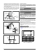
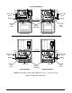
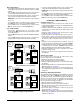
7. Remove the regulator capscrew from the INLET side of
the regulator. See (Figure 17, (page 20).
8. Slowly turn the adjustment screw inside the regulator to
obtain the appropriate manifold pressure.
NOTE: Turning the screw clockwise increases the pressure
and turning the screw counter-clockwise decreases the
pressure. To prevent backing the screw all the way out
from the valve, turn the screw slowly.
9. Replace and tighten the regulator capscrew over the
adjustment screw.
Verifying & Adjusting Temperature Rise
After installation of the furnace, confirm the temperature rise
of the furnace is within the limits specified on the rating plate.
Any temperature rise outside the specified limits could result
in premature failure of the heat exchanger.
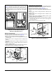
1. Place thermometers in the return and supply air stream
as close to the furnace as possible. The thermometer on
the supply air side must be shielded from direct radiation
from the heat exchanger to avoid false readings.
2. Adjust all registers and duct dampers to the desired position
and run the furnace for 10 to 15 minutes before taking
any temperature readings. The temperature rise is the
difference between the supply and return air temperatures.
For typical duct systems, the temperature rise will fall within the
limits specified on the rating plate with the blower speed at the
factory recommended setting. If the measured temperature
rise is outside the specified limits, it may be necessary to
change the speed of the blower. NOTE: Lowering the blower
speed will increase the temperature rise and a higher blower
speed will decrease the temperature rise.
The furnace is equipped with a multi-speed motor. Heating,
cooling, and fan speed selection is made by moving the switch
on the integrated control located in the furnace.
Verifying Burner Operation
CAUTION:
The door over the burners may only be open
for inspection purposes only. The door must be
installed during unattended operation.
1. Remove the burner compartment door.
2. Set the thermostat above room temperature and observe
the ignition sequence. NOTE: The burner flame should
carry over immediately between all burners without lifting
off, curling, or floating. The flames should be blue, without
yellow tips.
3. After validating the flame, change the thermostat setting
to below room temperature.
4. Verify the burner flame is completely extinguished.
5. Replace the burner compartment door.
Verify Operation of the Supply Air Limit Switch
A properly functioning limit switch should turn off the gas
valve when the return is blocked (time depends on how well
the return air is blocked). The circulating air and combustion
blowers should continue to run when the limit switch opens.
1. Verify the blower door is securely mounted in place and
that there is power to the furnace.
2. Block the return airflow to the furnace by installing a close-
off plate in place of or upstream of the filter(s).
3. Set the thermostat above room temperature and observe
the Operating Sequence.
4. Remove the close-off immediately after the limit switch
opens. If the furnace continues to operate with no return
air, set the thermostat below room temperature, shut off
power to the furnace, and replace the limit switch.
Capscrew
Figure 17. Regulator Capscrew