
J952V Installation Manual


41
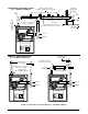
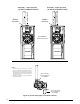
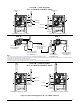
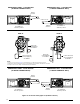
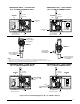
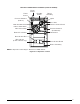
Figure 36. Component Locations
AIR FLOW
1 2 3
4
5 6 7
8
Burner
Assembly
Finish
Flange
Flame
Sensor
Igniter
Roll-Out
Switch
Gas Valve
Furnace Control Board
Pressure Switches
(Condensate)
Transformer
Motor Control Board
Blower Assembly
Motor Choke
(C & D cabinets only)
Blower Door Switch
Inducer Assembly
Pressure Switches
(Inducer)
Motor Control Box
Inducer Limit Switch
Main Air Limit Switch
UPFLOW / HORIZONTAL FURNACE (J952V*U SERIES)
NOTE: Component locations may be different in ‘A’ width cabinets.