Two-Stage Condensing gas Furnaces With Variable Speed Blowers 95.0% AFUE INSTALLATION INSTRUCTIONS J952V*U Upflow / Horizontal Furnace WARNING FIRE OR EXPLOSION HAZARD • Failure to follow safety warnings exactly could result in serious injury, death or property damage. • Installation and service must be performed by a qualified installer, service agency or the gas supplier. • Do not store or use gasoline or other flammable vapors and liquids in the vicinity of this or any other appliance.
TABLE OF CONTENTS IMPORTANT SAFETY INFORMATION...............................3 REQUIREMENTS & CODES...............................................3 Combustion Air Quality.....................................................4 Heating Load.....................................................................5 Installation in a Garage.....................................................5 Clearances to Combustible Materials...............................5 Operation of Furnace During Construction.................
IMPORTANT SAFETY INFORMATION INSTALLER: Please read all instructions before servicing this equipment. Pay attention to all safety warnings and any other special notes highlighted in the manual. Safety markings are used frequently throughout this manual to designate a degree or level of seriousness and should not be ignored. • • WARNING - indicates a potentially hazardous situation that if not avoided, could result in personal injury or death.
• A gas-fired furnace for installation in a residential garage must be installed as specified on page 5. • This furnace is not approved for installation in mobile homes. Installing this furnace in a mobile home could cause fire, property damage, and/or personal injury. • The Commonwealth of Massachusetts requires compliance with regulation 248 CMR 4.00 and 5.00 for installation of through – the – wall vented gas appliances as follows: 1.
Installation in a Garage This Gas-fired furnace may be installed in a residential garage with the provision that the burners and igniter are located no less than 18 inches (457mm) above the floor. The furnace must be located or protected to prevent physical damage by vehicles. WARNING: Do not place combustible material on or against the furnace cabinet or within 6 inches of the vent pipe.
COMBUSTION AIR & VENTING REQUIREMENTS WARNING: CARBON MONOXIDE POISONING HAZARD Failure to follow the steps outlined below for each appliance connected to the venting system being placed into operation could result in carbon monoxide poisoning or death. The following steps shall be followed with each individual appliance connected to the venting system being placed in operation, while all other appliances connected to the venting system are not in operation: 1.
IMPORTANT NOTE This safety device is a manually reset switch. DO NOT install jumper wires across these switches to defeat their function or reset a switch without identifying and correcting the fault condition. If a switch must be replaced, use only the correct sized part specified in the Replacement Parts List provided online. Direct Vent Systems Direct vent appliances draw combustion air from the outdoors and vent combustion products back outside, isolating the entire system from the indoor space.
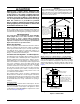
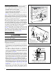
Outdoor Air Using Vertical Ducts If combustion air is taken from outdoors through vertical ducts, the openings and ducts must have a minimum free area of one square inch per 4,000 Btuh of total appliance input. See Figure 4. Vent or Chimney Ventilation Louvers at each end of attic Air Duct Water Heater Air Duct must be at least 1 sq. in. per 4,000 Btuh of total input rating. Vent or Chimney Attic Insulation Furnace Air Ducts must be at least 1 sq. in. per 2,000 Btuh of total input rating.
section (page 6). The length of vent and combustion air piping for either type of installation are shown in Table 1. Conventional Vent Systems - Unconfined Spaces An unconfined space is an area including all rooms not separated by doors with a volume greater than 50 cubic feet per 1,000 Btuh of the combined input rates of all appliances which draw combustion air from that space. In general, a furnace installed in an unconfined space will not require outside air for combustion.
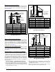
Vent Pipe Length & Diameter In order for the furnace to operate properly, the combustion air and vent piping must not be excessively restrictive. in. 18” M ax. 36” M • The venting system should be designed to have the minimum number of elbows or turns. • Transition to the final vent diameter should be done as close to the furnace outlet as practical. • Always use the same size or a larger pipe for combustion air that is used for the exhaust vent.
Exhaust Vent 12” Above Maximum Expected Snow Level (Both pipes) Combustion Air Elbows on the combustion air inlet must be positioned pointing away from the exhaust vent. Plumbing Vent Roof Boot (Both Pipes) in. 8" M ax. M " 36 Figure 10. Vertical Vent Termination • If venting horizontally, a side wall vent kit is available according to the pipe diameter size of the installation. For 2 inch pipe use side wall vent kit #904617, and for 3 inch pipe use kit #904347.
18 inches of vent pipe can be reduced. It is acceptable to reduce from 3” to 2-1/2”, 3” to 2”, or 2” to 1-1/2” if the total vent length is at least 15 feet in length and the vent length is within the parameters specified in Table 1. The restriction should be counted as 3 equivalent feet. Smaller vent pipes are less susceptible to freezing, but must not be excessively restrictive. The length of the 2 inch pipe must not be longer than 18 inches.
damper is in the cooling position and operation of the cooling system is prevented when the damper is in the heating position. • It is good practice to seal all connections and joints with industrial grade sealing tape or liquid sealant. Requirements for sealing ductwork vary from region to region. Consult with local codes for requirements specific to your area.
FURNACE INSTALLATION J952V*U series gas furnaces offer a wide range of installation options, including installation in the upflow or horizontal positions with either right, left, or upflow return air. General Requirements • The furnace must be leveled at installation and attached to a properly installed duct system. See Figure 1 (page 5) for the required clearances needed to move the furnace to its installation point (hallways, doorways, stairs, etc).
Inducer & Venting Options To increase installation flexibility, the inducer assembly can be rotated to 2 different positions (‘B’, ‘C’, & ‘D’ width cabinets only). Each variation has slightly different requirements with regard to condensate disposal and, in some cases, the need to seal the furnace cabinet. IMPORTANT NOTES • For ‘A’ width cabinets, the vent pipe can only exit the cabinet through the top of the cabinet.
Accessories The components in Figure 14 & Figure 15 are included in the extra parts bag supplied with the purchase of J952V*U furnaces. Depending on your particular installation, some of these components are optional and may not be used. Please refer to the descriptions and accompanying figures when installing these items. Finish Flange The finish flange must be installed to vent the combustion air pipe through the top of the furnace.
3. Install the 1/2” x 1/2” hose barb on the 2” PVC reducer. NOTE: Do not over tighten! Use an adequate amount of Teflon tape on the threads. Do not use liquid sealants. 4. Verify all connections and joints for tight fit and proper alignment with other vent pipes. Alternate Orientation 1. Install the 2” PVC Tee horizontally on the 2” vent pipe that is extending out the side of the cabinet. Permanently bond them together using appropriate primer and cement.
GAS SUPPLY & PIPING Door WARNING: Screws Wiring Harness Screws Blower Assembly Bottom Panel Front Brace Figure 16. Bottom Panel Removal Screws Blower Deck Door Bottom Panel Front Brace Screws Figure 17. Alternate Removal Method 18 FIRE OR EXPLOSION HAZARD • Failure to follow safety warnings exactly could result in serious injury or property damage. • Installation and service must be performed by a qualified installer, service agency or the gas supplier.
Manifold Automatic Gas Valvle (w/ Manual Shut-Off) Leak Check Burner Assembly WARNING: FIRE OR EXPLOSION HAZARD Failure to follow safety warnings exactly could result in serious injury or property damage. See Note “A” Shut-Off Valve See Note “B” Pipe Nipple Elbow Never test for gas leaks with an open flame. Use a commercially available soap solution made specifically for the detection of leaks to check all connections.
specifies the heating value at the residence’s gas meter as the “local value”. For added flexibility, two tables have been provided for natural gas installations with high or low heating values at sea level. Table 9 (page 30) & Table 10 (page 30) contain the orifice sizes and manifold pressure to use at various altitudes. Table 9 (HIGH) is for natural gas installations with a heating value of more than 1,000 Btu per cubic foot and Table 10 (LOW) is for less than 1,000 Btu per cubic foot.
ELECTRICAL WIRING IMPORTANT NOTE: WARNING: ELECTRICAL SHOCK, FIRE OR EXPLOSION HAZARD Failure to follow safety warnings exactly could result in serious injury or property damage. Improper servicing could result in dangerous operation, serious injury, death or property damage. • Before servicing, disconnect all electrical power to furnace. • When servicing controls, label all wires prior to disconnecting. Reconnect wires correctly. • Verify proper operation after servicing.
Grounding WARNING: To minimize personal injury, the furnace cabinet must have an uninterrupted or unbroken electrical ground. The controls used in this furnace require an earth ground to operate properly. Acceptable methods include electrical wire or conduit approved for ground service.
Autostaging for Single Stage Thermostats The Autostaging feature makes it possible to use a single stage thermostat and still receive some of the benefits of 2-stage furnace operation. If Autostage is enabled, the furnace will drop to LOW fire after initially starting in HIGH fire. After a period of 10 minutes, the furnace will then stage up to HIGH fire, until the heating load is met. See Figure 20 and the Low Voltage Connection section on page 22.
MOTOR CONTROL BOARD HUMIDISTAT c. DHUM DHUM R R Figure 23. DEHUM Wiring Configuration with Humidistat d. Using an Allen wrench, turn the the LO Input Adjusting Screw on the LO side of the regulator to adjust the reduced input setting or turn the HI Input Adjusting Screw on the side of the regulator to adjust the full input setting. See Figure 25 (page 24). NOTE: Turning the adjusting screw clockwise increases the pressure and counterclockwise reduces the pressure.
The furnace is equipped with a multi-speed motor. Heating and cooling speed selection is made by moving the switches on the integrated control located in the furnace. Verifying Burner Operation CAUTION: The door over the burners may only be open for inspection purposes only. The door must be installed during unattended operation. 1. Remove the burner compartment door. 2. Set the thermostat above room temperature and observe the ignition sequence.
Proper maintenance is most important to achieve the best performance from a furnace. Follow these instructions for years of safe, trouble free operation. • These maintenance instructions are primarily intended to assist qualified technicians experienced in the proper maintenance and operation of this appliance. • Always reinstall the doors on the furnace after servicing or cleaning/changing the filters. Do not operate the furnace without all doors and covers in place.
FIGURES & TABLES TOP VIEW J952V*U 95.1% UPFLOW / HORIZONTAL FURNACE DIM. “A” DIM. “B” DIM. “C” ‘A’ Cabinet 14 1/4 12 5/8 12 7/8 ‘B’ Cabinet 17 1/2 15 7/8 16 1/8 ‘C’ Cabinet 21 19 3/8 19 5/8 ‘D’ Cabinet 24 1/2 22 7/8 23 1/8 NOTE: Dimensions shown in inches.
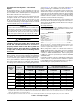
Gas Information GAS FLOW RATES (CUBIC FEET PER HOUR) TIME FOR ONE REVOLUTION (SECONDS) GAS FLOW RATES (CUBIC FEET PER HOUR) CUBIC FEET PER REVOLUTION OF GAS METER CUBIC FEET PER REVOLUTION OF GAS METER 1 5 10 TIME FOR ONE REVOLUTION (SECONDS) 1 5 10 10 12 360 300 1,800 1,500 3,600 3,000 66 68 55 53 273 265 545 529 14 257 1,286 2,571 70 51 257 514 16 225 1,125 2,250 72 50 250 500 18 200 1,000 2,000 74 49 243 486 20 180 900 1,800 76 47 237 474 22 164 818 1
HIGH ALTITUDE DERATION – PROPANE GAS INPUT (BTU) & STAGE ALTITUDE ABOVE SEA LEVEL 38,000 1ST 2ND 60,000 1ST 60 0 to 1,999 FT 4.2 2,000 to 2,999 FT 3,000 to 4,999 FT 5,000 to 5,999 FT 6,000 to 7,999 FT 8,000 to 10,000 FT 10.0 4.2 9.0 8.5 4.2 4.2 8.5 4.2 61 4.2 4.2 4.2 8.5 4.2 56 10.0 4.2 8.5 4.2 56 8.5 4.2 4.2 8.5 4.2 56 MANIFOLD PRESSURE ORIFICE SIZE 10.0 56 9.0 MANIFOLD PRESSURE ORIFICE SIZE 56 56 9.0 9.0 4.2 MANIFOLD PRESSURE ORIFICE SIZE 55 8.5 4.2 10.0 4.
HIGH ALTITUDE DERATION – NATURAL GAS WITH HIGH HEATING VALUE INPUT (BTU) & STAGE ALTITUDE ABOVE SEA LEVEL 38,000 1ST 0 to 1,999 FT 2,000 to 2,999 FT 3,000 to 3,999 FT 4,000 to 4,999 FT 5,000 to 5,999 FT 6,000 to 6,999 FT 7,000 to 7,999 FT 8,000 to 8,999 FT 9,000 to 9,999 FT 2ND 60,000 1ST 52 1.7 3.5 1.7 3.3 1.7 3.1 1.7 2.9 1.7 1.7 2.8 3.1 1.7 3.0 1.7 1.7 3.1 1.7 1.7 ORIFICE SIZE ORIFICE SIZE 3.5 3.3 1.7 3.0 1.7 MANIFOLD PRESSURE ORIFICE SIZE 48 2.
Electrical Information L2-OUT RED RED Y/Y2_OUT L1-IN DEHUMIDIFIER OUTPUT Y1_OUT NOT FOR FIELD USE OFF ON HUMIDIFIER OUTPUT H_OUT R L2-IN GREEN W_OUT FAN SPEED L1-OUT DHUM_IN 1 2 3 4 5 6 78 Y1_IN COOL HEAT SENSOR C GROUND EXPANSION PORT CONNECTION TO FURNACE CONTROL BOARD MOTOR WIRING HARNESS INPUT TERMINALS OUTPUT TERMINALS STATUS LIGHTS FOR USE WITH IQ OUTDOOR UNITS FOR WIRING TO THE MOTOR CONTROL BOARD R C W1 W2 G Y1 Y/Y2 Figure 27.
PRESSURE SWITCH DOOR SWITCH VENT LIMIT (ON SELECT MODELS) C BLACK 3 2 1 XMFR LINE EAC Figure 29. Wiring Diagram for Two-Stage, Variable Speed Upflow Furnaces L INDUCER H 6 5 4 9 8 7 1 2 3 4 5 1 2 3 1 2 3 WHITE BLACK 120 V BLWR OFF DELAY 1 1 2 2 LINE- N IGNITOR 1 2 3 4 5 6 BLUE BLACK WHITE BLUE ORANGE YELLOW GREEN BROWN RED Use copper conductors only.
Venting Information AIR SUPPLY INLET VENT TERMINAL AREA WHERE TERMINAL IS NOT PERMITTED CANADIAN INSTALLATIONS A US INSTALLATIONS B DIRECT VENT (2-PIPE) & CONVENTIONAL VENT (1-PIPE) FURNACES DIRECT VENT (2-PIPE) FURNACES CONVENTIONAL VENT (1-PIPE) FURNACES 12 inches (30cm) 12 inches (30cm) 12 inches (30cm) 6 inches (15cm) for appliances < 10,000 Btuh (3kW) 6 inches (15cm) for appliances < 10,000 Btuh (3kW) 12 inches (30cm) for appliances 10,000 Btuh - 100,000 Btuh (30kW) 9 inches (23cm) for
HORIZONTAL VENTING w/ 2-PIPES Straps or other suitable supports at minimum 5 ft. intervals (both pipes) (’A’ WIDTH CABINETS ONLY) Wall First support as close to furnace as possible 90° Elbows 90° Elbow COMBUSTION AIR VENT PIPE Flue Pipe must slope upward 1/4” per foot FLUE PIPE Rubber Grommet Seal / caulk around pipes at wall 7” 12” Min.
HORIZONTAL VENTING W/ 2-PIPES (B, C, & D WIDTH CABINETS) Straps or Other Suitable Supports at minimum of 5 ft. Intervals Seal/Caulk Around Pipes at Building 90° Elbow 90° Elbow 90° Elbow See Table 1 for 2” PVC pipe lengths (field supplied) Upward Pitch - 1/4” per foot (Flue Pipe) FLUE PIPE Coupling with 2 Hose Clamps (Optional) COMBUSTION AIR First support placed as close to furnace connection as possible Wall 12” Min.
Rubber Grommet COMBUSTION AIR COMBUSTION AIR FLUE PIPE Rubber Grommet FLUE PIPE UPFLOW - 2 PIPE OPTION (‘A’ WIDTH CABINETS ONLY) UPFLOW - 1 PIPE OPTION (‘A’ WIDTH CABINETS ONLY) See VIEW A for drain line positions OPTION 2 OPTION 1 VIEW -A- NOTES: 1. See Accessories section (page 15) for optional PVC Tee configurations and drainage options. 2. Drain tube must be trapped with a J-Trap or field supplied loop and drained externally from the cabinet.
UPFLOW - 1 PIPE OPTIONS (B, C, & D WIDTH CABINETS ONLY) PVC Trap Rubber Grommet OPTION 3 FLUE PIPE PVC Tee Plug See NOTE 3 FLUE PIPE X PVC Tee Plug COMBUSTION AIR COMBUSTION AIR X See NOTE 3 OPTION 4 PVC Trap Rubber Grommet See VIEW B for drain line positions See VIEW C for drain line positions VIEW -B- VIEW -C- Field Supplied Drain Line Attached to PVC Trap (Do Not Trap) Inline Drain Tube (Factory Supplied) See NOTE 4 Collector Box Drain (Factory Equipped) See NOTES 2 & 3 Inline Drai
HORIZONTAL RIGHT - 1 PIPE OPTION (’A’ WIDTH CABINETS ONLY) HORIZONTAL LEFT - 1 PIPE OPTION (’A’ WIDTH CABINETS ONLY) Rubber Grommet FLUE PIPE OPTION 7 OPTION 8 COMBUSTION AIR COMBUSTION AIR FLUE PIPE Rubber Grommet See VIEW D for drain line positions VIEW -D- See VIEW E for drain line positions VIEW -E- Inline Drain (Field Supplied) See NOTE 3 Inline Drain (Field Supplied) See NOTE 2 Collector Box Drain (Factory Equipped) See NOTE 2 Collector Box Drain (Factory Equipped) See NOTE 2 NOTES: 1.
HORIZONTAL LEFT - 1 PIPE OPTION (B, C, & D WIDTH CABINETS ONLY) Rubber Grommet OPTION 12 FLUE PIPE OPTION 11 FLUE PIPE HORIZONTAL RIGHT - 1 PIPE OPTION (B, C, & D WIDTH CABINETS ONLY) Rubber Grommet 1 2 34 5678 COMBUSTION AIR AIR FLOW COMBUSTION AIR See VIEW F for drain line positions See VIEW G for drain line positions Plug Plug Inline Drain (Factory Supplied) See NOTE 3 VIEW -FVIEW -GInline Drain (Field Supplied) See NOTE 2 Collector Box Drain (Factory Equipped) See NOTE 2 Collector Box
TROUBLESHOOTING FURNACE COMPONENTS If the furnace fails to operate check the following: • Is the thermostat operating properly? • Are the blower compartment door(s) in place? • Is the furnace disconnect closed? • Has the circuit breaker tripped or the control board fuse burned open? • Is the gas turned on? • Are any manual reset switches open? • Is the filter dirty or plugged? • Is the flame sensor coated? (Remove and clean with steel wool.
UPFLOW / HORIZONTAL FURNACE (J952V*U SERIES) Flame Sensor Finish Flange Roll-Out Switch Burner Assembly Igniter Pressure Switches (Inducer) Inducer Limit Switch AIR FLOW Main Air Limit Switch Gas Valve Furnace Control Board Pressure Switches (Condensate) Transformer Inducer Assembly Blower Door Switch Motor Control Box 1 2 34 5678 Motor Choke (C & D cabinets only) Motor Control Board Blower Assembly NOTE: Component locations may be different in ‘A’ width cabinets. Figure 36.
INSTALLATION CHECKLIST ELECTRICAL SYSTEM INSTALLER NAME: CITY: STATE: INSTALLATION ADDRESS: CITY: Electrical connections tight? YES NO Line voltage polarity correct? YES NO Supply Voltage:................................................................