
J952V Installation Manual

21
ELECTRICAL WIRING
WARNING:
ELECTRICAL SHOCK, FIRE OR
EXPLOSION HAZARD
Failure to follow safety warnings exactly could
result in serious injury or property damage.
Improper servicing could result in dangerous
operation, serious injury, death or property
damage.
• Before servicing, disconnect all electrical
power to furnace.
• When servicing controls, label all wires prior
to disconnecting. Reconnect wires correctly.
• Verify proper operation after servicing.
• Electrical connections must be in compliance with all
applicable local codes, and the current revision of the
National Electric Code (ANSI/NFPA 70).
• For Canadian installations the electrical connections and
grounding shall comply with the current Canadian Electrical
Code (CSA C22.1 and/or local codes).
IMPORTANT NOTE:
• If replacing any of the original wires supplied with
the furnace, the replacement wire must be copper
wiring and have a temperature rating of at least 105°F
(40°C). For electrical specifications, refer to the furnace
nameplate or
Table 4.
Line Voltage Wiring
It is recommended that the line voltage (115 VAC) to the
furnace be supplied from a dedicated branch circuit containing
the correct fuse or circuit breaker for the furnace. See
Table
4
below.
IMPORTANT NOTES:
• An electrical disconnect must be installed readily
accessible from and located within sight of the furnace.
See
Figure 19 or the wiring diagram label inside of
the control door. Any other wiring methods must be
acceptable to authority having jurisdiction.
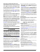
• Proper line voltage polarity must be maintained in order
for the control system to operate correctly. Verify the
incoming neutral line is connected to the white wire
and the incoming HOT line is connected to the black
wire. The furnace will not operate unless the polarity
and ground are properly connected as shown in
Figure
19
.
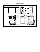
Figure 19. Line Voltage Field Wiring
Field Supplied
Disconnect within
Sight of Furnace
Field Supplied
Panel Connector
Field Supplied
Fused Service
Panel
Black (Hot)
White (Neutral)
Green or Bare (Ground)
Field Line Voltage Wiring
Factory Line Voltage Wiring
Ground
Ground
Junction Box (may be int. or ext. to the furnace). These connections can be made in the field supplied disconnect at the furnac
e.
NOTE:
Connections made within the furnace burner compartment do not require a junction box.
Ground
Black
White
Black
White
Black
White
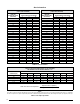
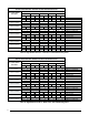
FURNACE
INPUT
(BTUH)
CABINET
WIDTH
(IN.)
NOMINAL
ELECTRICAL
SUPPLY
MAXIMUM
OPERATING
VOLTAGE
MINIMUM
OPERATING
VOLTAGE
MAXIMUM
FURNACE
AMPERES
MAXIMUM
FUSE OR CIRCUIT
BREAKER AMPS*
38,000 14 1/4 115-60-1 127 103 7.0 15
60,000 17 1/2 115-60-1 127 103 7.0 15
80,000 21 115-60-1 127 103 9.4 15
100,000 21 115-60-1 127 103 9.4 15
120,000 24 1/2 115-60-1 127 103 12.5 15
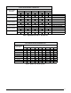
THERMOSTAT WIRE GAUGE
RECOMMENDED THERMOSTAT WIRE LENGTH
2 - WIRE - HEATING 4 OR 5 WIRE - COOLING
24 55 ft. 25 ft.
22 90 ft. 45 ft.
20 140 ft. 70 ft.
18 225 ft. 110 ft.
* Time-delay fuses or circuit breakers are required.
Table 4. Wire Length & Voltage Specifications