
J952V Installation Manual

25
The furnace is equipped with a multi-speed motor. Heating
and cooling speed selection is made by moving the switches
on the integrated control located in the furnace.
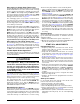
Verifying Burner Operation
CAUTION:
The door over the burners may only be open
for inspection purposes only. The door must be
installed during unattended operation.
1. Remove the burner compartment door.
2. Set the thermostat above room temperature and observe
the ignition sequence. The burner flame should carry over
immediately between all burners without lifting off, curling,
or floating. The flames should be blue, without yellow tips.
3. After validating flame characteristics, change thermostat
setting to below room temperature.
4. Verify burner flame is completely extinguished.
5. Replace the burner compartment door.
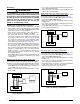
Verifying Operation of the Supply Air Limit
Switch
A properly functioning limit switch should turn off the gas
valve when the return is blocked (time depends on how well
the return air is blocked). The circulating air and combustion
blowers should continue to run when the limit switch opens.
1. Check the blower door for secure mounting and that there
is power to the furnace.
2. Block the return airflow to the furnace by installing a close-
off plate in place of or upstream of the filter(s).
3. Set the thermostat above room temperature and observe
the Operating Sequence.
4. Remove the close-off immediately after the limit switch
opens. If the furnace continues to operate with no return
air, set the thermostat below room temperature, shut off
the power to the furnace, and replace the limit switch.
OPERATING SEQUENCE
The operating sequences for the heating, cooling, and fan
modes are described below. Refer to the field and furnace
wiring diagrams:
Figure 19 (page 21), Figure 20 (page
22)
, Figure 21 (page 22), Figure 22 (page 22), & Figure
29 (page 32)
.
Heating Cycle
1. The thermostat calls for heat by energizing the W1 terminal
with 24VAC.
2. The control checks to see the pressure switch is open.
If the switch is closed, the furnace will shut down for 5
minutes before retrying
3. If the pressure switch is open, the control energizes the
inducer motor and waits for the pressure switch to close.
The pressure switch must close within 12 seconds.
4. The control runs the inducer for a 30 second pre-purge
time.
5. The control energizes the igniter output for the appropriate
adaptive warm-up time limit.
6. The furnace always ignites the burners in high fire. If the
call for heat is for low rate, the furnace will move down to
low fire after the flames stabilize.
7. If the flame is proved and ignites the gas, the control de-
energizes the igniter. The gas valve and inducer remains
energized. The control goes to blower on delay.
8. The control energizes the blower on the selected HEAT
speed 22 seconds after the gas valve opened. The gas
valve and inducer remain energized.
9. If there is a call for high fire, the gas valve moves to the
high fire position and the blower speeds are increased.
The furnace will remain in high fire until the demand for
heat is satisfied.
10. If autostaging is enabled (single stage thermostat) the
demand for heat has lasted more than the selected
time, the furnace automatically moves up to high fire.
Autostage time is ON (10 minutes) or OFF, depending
on the Jumper (P7) setting on the furnace control board.
11. When the thermostat demand for heat is satisfied, the
control de-energizes the gas valve. The inducer output
remains on for a 30 second post-purge period.
12. The circulating air blower will continue to run for the
selected Blower Off Delay(P5). This may be 60, 90, or
120 seconds depending on the jumper setting on the
furnace control board.
Cooling Cycle
1. The thermostat calls for cooling by energizing the Y / Y2
or Y1 terminal with 24VAC.
2. The control energizes the blower in the cooling speed and
sends 24VAC to the contactor in the condensing unit.
3. When the thermostat removes the call for cooling, the
contactor in the outdoor condensing unit is de-energized
and the control continues to run the fan for a period of 60
seconds.
Fan Mode
• When the thermostat energizes the G terminal for
continuous fan (without calling for heat or cooling), the
indoor fan is energized on the selected FAN speed.
• If a call for cooling occurs during continuous fan, the blower
will switch over to the selected COOL speed.
• If the W terminal receives a call for heat during continuous
fan, the blower will de energize.
• A call for fan is ignored while in lockout.
• For continuous fan operation, the variable speed blower
motor will operate at 50% of the high-speed CMF.
MAINTENANCE
WARNING:
ELECTRICAL SHOCK, FIRE OR
EXPLOSION HAZARD
Failure to follow safety warnings exactly could
result in serious injury or property damage.
Improper servicing could result in dangerous
operation, serious injury, death or property
damage.
• Before servicing, disconnect all electrical
power to furnace.
• When servicing controls, label all wires prior
to disconnecting. Reconnect wires correctly.
• Verify proper operation after servicing.