
J952V Installation Manual

39
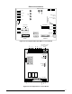
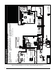
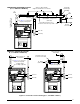
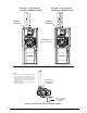
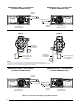
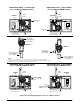
Figure 35. Horizontal Venting Options (B, C, & D Width Cabinets)
Plug
OPTION
13
OPTION
14
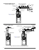
Inline Drain
(Field Supplied)
See NOTE 2
Collector Box Drain
(Factory Equipped)
See NOTE 2
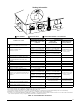
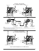
VIEW -F-
VIEW -G-
Inline Drain
(Factory Supplied)
See NOTE 3
FLUE PIPE
AIR FLOW
1 2 3
4
56 7
8
COMBUSTION
AIR
HORIZONTAL RIGHT - 1 PIPE OPTION
(B, C, & D WIDTH CABINETS ONLY)
FLUE PIPE
COMBUSTION
AIR
Rubber
Grommet
Rubber
Grommet
Plug
FLUE PIPE
Rubber
Grommet
COMBUSTION AIR
FLUE PIPE
AIR FLOW
1 2 3
4
56 7
8
Rubber
Grommet
COMBUSTION AIR
See VIEW F for
drain line positions
See VIEW F for
drain line positions
See VIEW G for
drain line positions
Plug
Plug
See VIEW G for
drain line positions
Flange
Flange
OPTION
11
OPTION
12
HORIZONTAL LEFT - 1 PIPE OPTION
(B, C, & D WIDTH CABINETS ONLY)
HORIZONTAL LEFT - 2 PIPE OPTION
(B, C, & D WIDTH CABINETS ONLY)
HORIZONTAL RIGHT - 2 PIPE OPTION
(B, C, & D WIDTH CABINETS ONLY)
Collector Bo
x Drain
(Factor
y Equipped)
See NOTE 2
NOTES:
1. See Accessories section (page 15) for optional PVC Tee configurations and drainage options.
2. All drain lines must be trapped with J-Trap or field supplied loop and drained externally from the cabinet.
3. Tubing needs to be cut to length and attached during unit installation.