
J952V Installation Manual

10
Vent Pipe Length & Diameter
In order for the furnace to operate properly, the combustion
air and vent piping must not be excessively restrictive.
• The venting system should be designed to have the
minimum number of elbows or turns.
• Transition to the final vent diameter should be done as
close to the furnace outlet as practical.
• Always use the same size or a larger pipe for combustion
air that is used for the exhaust vent.
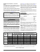
Table 1 indicates the maximum allowable pipe length for a
furnace of known input rate, when installed with piping of
selected diameter and number of elbows. To use the table,
the furnace input rate, the centerline length and the number
of elbows on each pipe must be known.
When estimating the length of vent runs, consideration must
be made to the effect of elbows and other fittings. This is
conveniently handled using the idea of “equivalent length”.
This means the fittings are assigned a linear length that
accounts for the pressure drop they will cause. For example:
a 2” diameter, long radius elbow is worth the equivalent of
2.5 feet of linear run. A 90 degree tee is worth 7 ft.
The equivalent lengths of tees and various elbows are listed
in
Table 1 . Measure the linear length of the vent run and
then add in the equivalent length of each fitting. The total
length, including the equivalent fitting lengths, must be less
than the maximum length specified in
Table 1.
Vent Pipe Installation
CAUTION:
Combustion air must not be drawn from a
corrosive atmosphere.
This furnace has been certified for installation with zero
clearance between vent piping and combustible surfaces.
However, it is good practice to allow space for convenience
in installation and service.
• In the absence of local codes, the location of any combustion
air inlet relative to any vent terminal must be at least 8
inches. This includes installations involving more than one
furnace.
• The quality of outdoor air must also be considered. Be
sure that the combustion air intake is not located near
a source of solvent fumes or other chemicals which can
cause corrosion of the furnace combustion system. (See
list of substances on
page 5).
• Route piping as direct as possible between the furnace
and the outdoors. Horizontal piping from inducer to the flue
pipe must be sloped 1/4” per foot to ensure condensate
flows towards the drain tee or PVC trap. Longer vent runs
require larger pipe diameters. Refer to the Inducer & Venting
Options section on
page 15 for additional information.
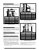
• If a Direct Vent (2-pipe) system is used, the combustion air
intake and the vent exhaust must be located in the same
atmospheric pressure zone. This means both pipes must
exit the building through the same portion of exterior wall
or roof as shown in
Figure 7, Figure 8, Figure 9, & Figure
10 (page 11)
.
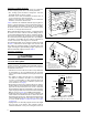
• Piping must be mechanically supported so that its weight
does not bear on the furnace. Pipe supports must be
installed a minimum of every 5 feet along the vent run to
Figure 9. Alternate Horizontal Vent Installation
Support
NOTE: Vent Configuration to Provide
12" Minimum height above Snow Level.
1/2"
Armaflex
Insulation or
Equivalent
(if required)
12" Above
Maximum
Expected
Snow Level
19" Max.
(See Note)
Outside
Wall
12” min. to maximum
expected snow level
(both pipes)
90° Elbow
Exhaust vent
option B
Exhaust vent
option A
Mounting kit faceplate
secured to wall with screws
(both pipes)
Combustion
air inlet
Exhaust vent
option C
18” Min.
36” Max.
8” Min.
36” Max.
(all positions)
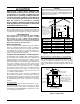
Figure 7. Inlet & Exhaust Pipe Clearances
Note 2
Mechanical draft
vent terminal
Direct vent
terminal
50,000 Btuh
or less
Forced air inlet
Direct vent
terminal - more
than 50,000 Btuh
Mechanical
draft vent
terminal
Mechanical
draft vent
terminal
Less
than
10 ft.
3 ft.
NOTES:
1. All dimensions shown are
minimum requirements.
2. Exterior vent terminations must
be located at least 12” above the
maximum expected snow level.
Note 2
4 ft
4 ft
12 in.
12 in.
9 in.
Note 2
Figure 8. Vent Locations