
J952V Installation Manual

9
Conventional Vent Systems - Unconfined
Spaces
An unconfined space is an area including all rooms not
separated by doors with a volume greater than 50 cubic feet
per 1,000 Btuh of the combined input rates of all appliances
which draw combustion air from that space.
In general, a furnace installed in an unconfined space will
not require outside air for combustion. However, in homes
built for energy efficiency (low air change rates), it may
be necessary to provide outside air to ensure adequate
combustion and venting, even though the furnace is located
in an unconfined space. See
Example below.
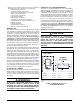
EXAMPLE
A space with a water heater rated at 45,000 Btuh input
and a furnace rated at 75,000 Btuh requires a volume of
6,000 cubic feet [50 x (45 + 75) = 6,000] to be considered
unconfined. If the space has an 8 foot ceiling, the floor
area of the space must be 750 sq. ft. (6,000 / 8 = 750).
Category IV Venting
WARNING:
Upon completion of the furnace installation,
carefully inspect the entire flue system both
inside and outside the furnace to assure it is
properly sealed. Leaks in the flue system can
result in serious personal injury or death due
to exposure of flue products, including carbon
monoxide.
This furnace is classified as a “Category IV” appliance,
which requires special venting materials and installation
procedures. This section specifies installation requirements
for Conventional (1-pipe) and Direct Vent (2-pipe) piping.
For 1- pipe installations, install vent piping as described in
this section and provide air for combustion and ventilation
according to the Combustion Air & Venting Requirements
section (page 6). The length of vent and combustion air
piping for either type of installation are shown in
Table 1.
Category IV appliances operate with positive vent pressure
and therefore require vent systems which are thoroughly
sealed. They also produce liquid condensate, which is slightly
acidic and can cause severe corrosion of ordinary venting
materials. Furnace operation can be adversely affected by
restrictive vent and combustion air piping.
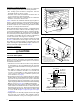
The inducer assembly on this furnace can be rotated to vent
the flue products out of the left or right side of the furnace.
This increases the flexibility of which direction the vent pipe
can exit the furnace.
Vent Pipe Material
Vent and combustion air pipe and fittings must be one of
the following materials in the list and must conform to the
indicated ANSI/ASTM standards.
MATERIALS STANDARDS
Schedule 40PVC ............................................................... D1785
PVC-DWV .......................................................................... D2665
SDR-21 & SDR-26 ............................................................. D2241
ABS-DWV .......................................................................... D2661
Schedule 40 ABS .............................................................. F628
Foam / Cellular Core PVC ................................................. F891
*PolyPro
®
by DuraVent ...................................................... ULC-S636
CPVC ................................................................................. D1784
*When using PolyPro
®
, all venting and fittings must be from the same
manufacturer with no interchanging of other materials. Refer to specific
instructions supplied with the PolyPro vent kits
When joining PVC to PVC, use cement that conforms to
ASTM standard D2564. PVC primer must meet standard
ASTM F656. When joining ABS to ABS, use cement that
conforms to ASTM standard D2235. When joining PVC
to ABS, use cement as specified in procedure from ASTM
standard D3138
In Canada, all plastic vent pipes and fittings including any
cement, cleaners, or primers must be certified as a system
to ULC S636. However this requirement does not apply to
the finish flanges or piping internal to the furnace.
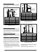
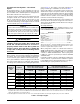
Table 1. Vent Pipe Lengths
FURNACE
MODELS
(BTU)
FURNACE
INSTALLATION
SINGLE VENT PIPE LENGTH (FT.)
WITH 1 LONG RADIUS ELBOW*
DUAL VENT PIPE LENGTH (FT.)
WITH 1 LONG RADIUS ELBOW ON EACH PIPE*
OUTLET
2” DIAMETER
OUTLET
3” DIAMETER
INLET / OUTLET
2” DIAMETER
INLET / OUTLET
3” DIAMETER
38,000
Upflow 90 90 90 90
Horizontal 50 90 50 90
60,000
Upflow 90 90 90 90
Horizontal 50 90 50 90
80,000
Upflow 40 90 40 90
Horizontal 30 90 30 90
100,000
Upflow 30 90 30 90
Horizontal 30 90 30 90
120,000
Upflow N/A 90 N/A 90
Horizontal N/A 90 N/A 90
*NOTES:
1. Subtract 2.5 ft. for each additional 2 inch long radius elbow, 5 ft. for each additional 2 inch short radius elbow, 3.5 ft. for each additional 3 inch
long radius elbow, and 7 ft. for each additional 3 inch short radius elbow. Subtract 5 ft for each 2” tee and 8 ft for each 3” tee. Two 45 degree
elbows are equivalent to one 90 degree elbow.
2. This table applies for elevations from sea level to 2,000 ft. For higher elevations, decrease pipe lengths by 8% per 1,000 ft of altitude.