/4” 18-GAUGE CROWN AIR STAPLER Model 68018 SET UP AND OPERATING INSTRUCTIONS Visit our website at: http://www.harborfreight.com Read and understand tool labels and manual. Failure to follow warnings could result in DEATH or SERIOUS INJURY. SAVE THIS MANUAL. Copyright© 2010 by Harbor Freight Tools®. All rights reserved. No portion of this manual or any artwork contained herein may be reproduced in any shape or form without the express written consent of Harbor Freight Tools.
SAVE THIS MANUAL Keep this manual for the safety warnings and precautions, assembly, operating, inspection, maintenance and cleaning procedures. Write the product’s serial number in the back of the manual near the assembly diagram (or month and year of purchase if product has no number). Keep this manual and the receipt in a safe and dry place for future reference.
WARNING – When using tools, basic precautions should always be followed, including the following: c. Avoid unintentional starting. Be sure the trigger is released before connecting to the air supply. Do not carry the tool with your finger on the trigger or connect the tool to the air supply with the trigger pressed. d. Do not overreach. Keep proper footing and balance at all times. Proper footing and balance enables better control of the tool in unexpected situations. e. Use safety equipment.
Never carry the tool with finger on trigger, the tool is able to fire a fastener. h. Use only accessories that are identified by the manufacturer for the specific tool model. Use of an accessory not intended for use with the specific tool model, increases the risk of injury to persons. i. Use only those fasteners listed in the Specifications chart of this manual.
SAVE THESE INSTRUCTIONS. Specific Safety INSTRUCTIONS Instructions SAFETY 1. Operators and others in work area MUST wear ANSI-approved safety goggles with side shields during use. The employer is responsible to enforce the use of eye protection by the operator and others in the work area. 2. Keep fingers away from Trigger (32) when not driving fasteners to avoid accidental firing. 3. Choice of triggering method is important. Check manual for triggering options. 4.
23. Install in-line shutoff valve to allow immediate control over air supply in an emergency, even if a hose is ruptured. 24. Do not engrave or stamp anything into the housing to avoid weakening it. 25. WARNING: Some dust created by power sanding, sawing, grinding, drilling, and other construction activities, contains chemicals known [to the State of California] to cause cancer, birth defects or other reproductive harm.
to the Assembly Diagram near the end of this manual. FUNCTIONAL DESCRIPTION Functional Description Specifications Unpacking Maximum Air 120 PSI Pressure Air Inlet 1/4”-18 NPT Fastener Type Magazine Capacity 5/8” to 1-5/8”, 18 Gauge, 1/4” Crown Staples Safety Single Sequential When unpacking, make sure the item is intact and undamaged. If any parts are missing or broken, please call Harbor Freight Tools at 1‑800‑444‑3353 as soon as possible.
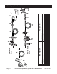
Page 8 A B C D E F G H Air Hose Filter Regulator Lubricator (optional) Coupler and Plug Leader Hose (optional) Air Cleaner / Dryer (optional) Air Adjusting Valve (optional) Description Non-lubricated Tools A Lubricated Tools B B G D C A Function A E E F Connects air to tool Prevents dirt and condensation from damaging tool or work piece Adjusts air pressure to tool For air tool lubrication Provides each connections Increases coupler life Prevents water vapor from damaging work piece For fine
B A SKU 68018 A B C D E F G H I J K L M N O Description F E F Vibration Pads Anchor Bolts Ball Valve Isolation Hose Main Air Line - 3/4” minimum recommended Ball Valve Branch Air Line -1/2” minimum recommended Filter Air Cleaner / Dryer (optional) Regulator Lubricator Air Hose Coupler and Plug Air Adjusting Valve Leader Hose B A C D G H H J I K J L M Function L M O N For noise and vibration reduction Secures air compressor in place Isolates sections of system for maintenance For vibra
tool. Other components, such as coupler plug and industrial-grade quick coupler, will make operation more efficient, but are not required. WARNING! TO PREVENT SERIOUS INJURY FROM ACCIDENTAL OPERATION: Do not install a quick coupler on the tool. A coupler contains an air valve that will allow the air tool to retain pressure and operate accidentally after the air supply is disconnected. Note: Air flow, and therefore tool performance, can be hindered by undersized air supply components. 3.
parts. If any problems are found, do not use tool until repaired. again. The tool must not cycle (fire). If it fails to act in the manner explained in bold, have it repaired by a qualified service technician. Testing the Single Sequential Safety Trip Mechanism Loading Staples Even though the Stapler should be empty during this procedure, ALWAYS point the Stapler at a piece of scrap wood when testing. 1. Make sure the tool is disconnected from the power supply. 2.
4. To fire, open the shut-off valve, place the Safety against the workpiece. The Stapler should not fire if the nose is not depressed. Once depressed, gently and briefly squeeze the Trigger once. Do not fire repeatedly. Staples could bounce off of one another, damaging the work piece or causing PERSONAL INJURY. 5. Adjust position of the Air Deflector (3) to direct exhaust away from yourself. 6.
USER-MAINTENANCE User-Maintenance Instructions Procedures not specifically explained in this manual must be performed only by a qualified technician. Note: These procedures are in addition to the regular checks and maintenance explained as part of the regular operation of the air-operated tool. Daily - Air Supply Maintenance: Every day, perform maintenance on the air supply according to the component manufacturers’ instructions.
3. Hold the Stapler pointed away from you and any other people or fragile objects and lift up the Cover Latch (43). 4. Pull up on the Switch, lifting the Cover Plate (44) up off the Drive Guide (41) and remove jammed fasteners. 5. Inspect Drive Guide for bends or breakage. If it is damaged, do not use tool until it is repaired by a qualified technician. 6. Lightly oil Drive Guide and replace the Cover Plate (57). 7.
Troubleshooting Troubleshooting Problem Possible Causes Insufficient fastener depth. 1. Not enough air pressure. 2. Incorrect lubrication or not enough lubrication. 3. Blocked air inlet screen (if equipped). 4. Mechanism contaminated. Likely Solutions 1. Check for loose connections and make sure that air supply is providing enough air pressure (PSI) to the tool’s air inlet. Do not exceed maximum 120 PSI air pressure. 2. Lubricate using air tool oil and grease according to directions. 3.
PLEASE READ THE FOLLOWING CAREFULLY THE MANUFACTURER AND/OR DISTRIBUTOR HAS PROVIDED THE PARTS LIST AND ASSEMBLY DIAGRAM IN THIS MANUAL AS A REFERENCE TOOL ONLY. NEITHER THE MANUFACTURER OR DISTRIBUTOR MAKES ANY REPRESENTATION OR WARRANTY OF ANY KIND TO THE BUYER THAT HE OR SHE IS QUALIFIED TO MAKE ANY REPAIRS TO THE PRODUCT, OR THAT HE OR SHE IS QUALIFIED TO REPLACE ANY PARTS OF THE PRODUCT.
ASSEMBLY DIAGRAM Assembly Diagram 1 67 2 68 14 3 4 71 70 69 15 5 57 16 6 17 24 23 25 26 28 31 19 10 30 39 36 11 63 62 64 4 60 41 40 48 59 58 57 49 56 51 47 21 43 38 61 5 42 13 46 34 20 12 27 33 29 35 37 31 32 27 27 18 8 65 66 22 7 9 72 44 45 46 50 52 53 55 54 Record Product’s Serial Number Here: Note: If product has no serial number, record month and year of purchase instead.
Limited 1 Year Warranty Harbor Freight Tools Co. makes every effort to assure that its products meet high quality and durability standards, and warrants to the original purchaser that this product is free from defects in materials and workmanship for the period of one year from the date of purchase (90 days if used by a professional contractor or if used as rental equipment).