TM www.datawatchtech.com DataTale SMART 2‐Bay RAID System Smart and user-friendly data management experience User’s Manual USB 2.0 eSATA FireWire 400 FireWire 800 Please go onto Data Watch website at http://www.datawatchtech.com for the latest version of user manual. 7 Rev.
Table of Contents GENERAL INFORMATION ..............................................................................................4 Copyright......................................................................................................................................................................4 Notices And Classifications...................................................................................................................................4 Contact Us ..............................
PC.......................................................................................................................................................................................36 MAC...................................................................................................................................................................................36 DISK VOLUME OVER 2TB.............................................................................................36 RAID MODES............
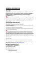
GENERAL INFORMATION Copyright Copyright @ 2011 Data Watch Technologies Co., Ltd. All rights reserved. No part of this publication may be reproduced, stored in a retrieval system, or transmitted in any form or by any means, electronic, mechanical, photocopying, recording or otherwise, without the prior written consent of Data Watch Technologies Co., Ltd. The product information provided in this manual is subject to change without prior notice and does not represent a commitment on behalf of the vendor.
PRECAUTIONS FOR THE RAID SYSTEM General Precautions ¾ The main circuit board of the RAID System is susceptible to static electricity. Proper grounding is required to prevent electrical damage to the RAID System or other connected devices, including the host computer. Always place the RAID System on a smooth surface and avoid all dramatic movement, vibration and percussion.
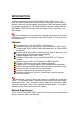
INTRODUCTION Thank you for purchasing the DataTale SMART 2-Bay RAID System. The DataTale SMART RAID System with RAID MASTER (Graphic User Interface) provides substantial storage capacity and distinctive RAID configuration options in a desktop storage device. The RAID MASTER allows easy configuration of RAID Modes: JBOD (None RAID), RAID 0 (Striping), RAID 1 (Mirroring), and Span (Large). Please thoroughly read and follow the instructions provided in this manual.
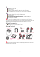
PC 500MHz or faster CPU 512MB of RAM Microsoft Windows 2000, XP, 2003, Vista, 2008, 7 or higher One available eSATA, USB 2.0, IEEE 1394a, or IEEE 1394b port MAC Macintosh PowerPC or Intel Core Duo processor 512MB of RAM Mac OS X 10.4 (Intel/PowerPC) or higher One available eSATA, USB 2.0, IEEE 1394a, or IEEE 1394b port Time Machine Compatible 3.5-inch SATA compatible hard drive is required for the RAID System.
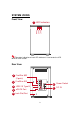
SYSTEM VIEWS Front View 1 LED Indicators Disk 1 Disk 2 Power The status indication of each LED indicator is listed under the LED INDICATORS section. Rear View 2 FireWire 800 (2 ports) 3 FireWire 400 6 Power Switch eSATA 5 eSATA Port DC IN 4 USB 2.
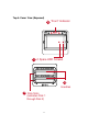
Top & Cover View (Exposed) 10 “Front” Indicator 9 11 2 Spare HDD Screws 13 Handles 12 Disk Slots (indicates Disk 1 through Disk 2) 9
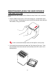
INSERTING/REPLACING THE HARD DRIVES IN THE RAID SYSTEM To assemble the RAID System, please follow the steps listed in the instructions below: 1. Place the RAID System with its Front View facing you. Position both hands on the front edge. Simultaneously, push the lid in the direction away from you, front to back, using your thumbs. A “click” sound would indicate release of the top lid’s security clasp. 2. Lift the top lid up to remove and expose the Top View (or Disk slots).
Fasten The Handle Onto The Hard Disk 3. Place the hard disk with the metal cover side facing up and ensure that the interface connectors are oriented toward your left side. Connectors 4. Position the handle to the hard disk end, which is facing away from the interface connectors, and align it with the screw hole openings.
5. Fasten the handle onto the hard disk by inserting and tightening the screws, the left one first, then the right one. Right Left 6. Now, flip the hard disk so it is facing you with the PCBA (Printed Circuit Board) on top and the unfasten handle side facing you.
7. Insert and tighten the screws, the left one first, then the right one. Right Left 8. Finally, test sliding the handle to make sure the holes glide smoothly on the screw guides. Repeat the same procedures for the second hard disk. The auto-limiting segmented screws are designed to prevent the hard disks or/and the handles from damages due to over-tightening. Furthermore, this design makes the handle slide easily without any tightness.
Place The Hard Disk Inside The RAID System 9. Hold the HDD with the metal cover side facing you and the handle attached on the upward position. If the HDD is inserted on its reverse side, the SmartGuider* System won’t be able to align and the HDD cannot be inserted. 10. Align the handle with the guide rails and slide the HDD into the indicated slot. Firmly push downward until a “thump” sound is heard. Repeat the same procedures for the second HDD.
11. Place the RAID System with its Front View facing you and the top lid on. Position both hands on the back edge of the top lid. Simultaneously, push the lid firmly downward and toward you, back to front. A “click” sound would indicate grasp of the top lid security clasp. 12.
CONNECTING THE RAID SYSTEM TO A COMPUTER To connect the RAID System, please complete the following steps: DC IN eSATA 1. Connect the AC/DC Power Adapter. DC IN eSATA 2. Insert both ends of the USB 2.0, eSATA, FireWire 400, or FireWire 800 cable(s) into the corresponding port of the RAID System and the host. The RAID System should only be connected to a host computer via one interface.
DC IN eSATA 3. Turn the Power Switch to the “on” position. 4. When connected, the Power LED light will become steadily green. If the HDDs are inside the RAID System, the Disk LED lights will become steadily white. If there are no HDDs inside the RAID System, the Disk LED lights will not turn on.
5. You are now ready to begin using your RAID System! Installing HDDs OK! Due to compatibility issues, if you use the eSATA interface to do the data transfer, the Silicon Image eSATA host controller is highly recommended. When using FireWire 800, you can “Daisy chain” and connect other computer hardware or digital devices to your System (such as digital video camera, another HDD, DVD writer, and much more). Please see “Daisy Chain” under “Q&As” Section for more information.
RAID MASTER The RAID MASTER is a newly-designed GUI Software specifically for our DataTale SMART RAID System. The drivers of the RAID MASTER for both PC and MAC are provided via CD included in the Package. The RAID MASTER provides a more convenient yet modern way to manage your RAID System.
RAID MASTER MENU CONFIGURATION & REBUILD: o Shows a single connected RAID System, or multiple connected RAID Systems. o Supports RAID configurations under Configuration and Rebuild options o Provides hard disk(s)’ current RAID status o Indicates individual hard disk (s)’ current disk information DEVICE INFORMATION: o Provides the basic information of the RAID System itself, once the RAID System is connected to the host: the Device’s information, and serial number for each inserted hard disks.
CONFIGURATION & REBUILD Create A RAID To setup RAID functions for the RAID System, please complete the following steps: Creating a new RAID mode will delete all data stored on the hard disk(s). If you have important saved data in the hard drives, backup all data before formatting the RAID Mode. 1. Under the “Configuration” option tab, select the RAID mode preferred and click the “Create RAID/Apply” icon.
RAID MASTER’S “Create RAID/Apply” icon will not be available to click (faint image). If the OS of the host can support more than 2TB hard disk(s) storage capacities and the hard disk(s) is/are over 2TB, remember to check the “Over 2TB” option under the “Configuration” option tab. Please see “Over 2TB” section under Q&As for more information. Please review the “DISK VOLUME OVER 2TB” section of the User’s Manual for OS support information. 2.
Changing The Most Recent Assigned RAID Mode To change the most recent assigned RAID Mode for the inserted hard disk(s) of the RAID System, please complete the following steps: Changing the RAID Mode will delete all data stored on the hard disk(s). If you have important saved data in the hard drives, backup all data before changing the RAID Mode. 1. Under the “Configuration” option tab, select the RAID mode prefer changing to and click the “Create RAID/Apply” icon.
2. Once selected, the RAID MASTER will give an alert popup window stating, “all data on disk will be lost. Proceed?” Click on “Yes” icon to confirm. 3. Once confirmed, the RAID MASTER will begin processing the chosen RAID Mode onto the chosen hard disk(s). Once the process is completed, the “RAID Status” and “Disk Information” should reflect the newly assigned RAID mode.
Deleting An Assigned RAID Mode To delete an assigned RAID Mode for the inserted hard disk(s) of the RAID System, please complete the following steps: Deleting a RAID Mode will delete all data stored on the hard disk(s). If you have important saved data in the hard drives, backup all data before deleting the RAID Mode. 1. Under the “Configuration” option tab, click the “Delete RAID” icon to change the hard disk(s) into JBOD (None RAID) disks.
2. Once selected, the RAID MASTER will give an alert popup window stating, “all data on disk will be lost. Proceed?” Click on “Yes” icon to confirm. 3. Once confirmed, the RAID MASTER will begin erasing the old RAID Mode for the chosen hard disk(s). Once the process is completed, the “RAID Status” and “Disk Information” should reflect the chosen hard disk(s) as JBOD (None RAID).
Rebuild To setup Rebuild under RAID 1 mode, please complete the following steps: The use of identical hard disks from the same manufacturer, with the same capacity and RPM is highly recommended. 1. Under RAID 1 mode, if one of the hard disks fails or a hard disk is removed, a popup window stating “Attention! Hot Swap” will appear. Click on “Ok” icon to continue. 2. Another popup window will appear stating, “Attention! RAID 1 Degrade Mode”. Click on “Ok” to continue.
3. Then, the “Rebuild” option should appear. Continue by replacing the failed hard disk with a functional disk or inserting a New disk in place of the one removed. The New disk will show up as red “New” and “Not Config”. To rebuild the New disk (the new functional disk) with the data from the Old disk (the remaining functional disk) sector by sector, click on the “Rebuild ==>” icon. The New disk may be inserted into either Disk 1 or Disk 2, because the Rebuild feature can be performed in either direction.
4. A popup window stating, “Copy Data From Disk 1 to Disk 2. All data in Disk 2 will be lost. Continue?” Click on the “Yes” icon to confirm. 5. During the rebuild, a “Rebuild Percentage” status window will appear and the information under “RAID Status” and “Disk Information” sections should reflect the same. If data is accessed while the chipset is processing the Rebuild task, the speed of data access may vary or decrease. Hence, data access of the hard disk(s) during Rebuild is highly not recommended.
After the rebuild is completed, data from Old disk will be copied onto the New disk under RAID 1 mode. The Rebuild feature is only available under RAID 1 mode. If the “Rebuild” option tab is selected under any other RAID mode, a popup window will appear stating, “Attention! There should be two disks with at least one RAID 1 disk for Rebuild Mode.
Mixed RAID Statuses When a New disk that’s been formatted with a certain RAID mode in another RAID System and is placed into the current RAID System along with an existing disk, a “Mixed RAID” status will result. Under this circumstance, the New disk can be re-formatted as JBOD (None RAID) mode. To do so, please complete the following steps: 1. The New disk will appear as “RAID 0 (Broken)”, or other variations depending on the situation for other RAID modes.
3. Once completed, the New disk is ready to be used as JBOD or combined with the existing disk under a chosen RAID mode.
Device Information To retrieve Device Information for the inserted disk(s) of the RAID System(s), please connect the RAID System(s) to the host and open the RAID MASTER. Once connected, click on the second sub-menu icon (bottom) to see the information: The connected RAID System(s) information with Device model of the RAID System(s), and serial numbers of each inserted hard disks.
NUMBER OF DISKS SUPPORTING EACH RAID MODE RAID Modes Number of Disk in RAID RAID 0 (Striping) RAID 1 (Mirroring) Span (Large) JBOD (None RAID) 2 2 2 1 to 2 DISK SLOT NUMBER 2 1 LED INDICATORS Disk 1 Disk 2 Power Power LED x 1 Indicators Power on Power off Color Green None 34
DISK LED x 4 There are 2 LEDs for each disk slot. The left LED indicates “Connection” and the right one indicates “Health/Access”. The Connection LED is only one-color (white). When the hard disk is connected, the white LED will be on. The Connection LED also indicates hard disk power status and disk rebuild status. When the target disk is being rebuilt, the white LED will blink. The Health/Access LED is dual-color (red/blue). The red color is for Health condition. The blue color is for Access condition.
EXTERNAL BOOTUP External Bootup may be required if the user has two different operating systems set up in both the host computer and the RAID System. PC The External Bootup with different interface: OS \ Interfaces USB 2.0 FireWire Windows No No DOS Yes No eSATA Yes Yes MAC The External Bootup varies with different platform and interfaces: eSATA Platform \ Interfaces USB 2.
RAID MODES A Redundant Array of Independent (or Inexpensive) Disks (RAID) is a system that utilizes multiple hard drives to share or replicate data among the disks. The benefit, depending on the selected RAID Mode (combinations of disks), is one or more of increased data integrity, fault-tolerance, throughput or capacity when compared to single drives. Deleting the current partition prior to changing RAID modes is highly recommended.
RAID 1 (Mirroring) RAID 1 (Mirroring) consists of at least two drives storing duplicate copies of the same data. In this mode, the data is simultaneously written to two disks. Thus, the storage capacity of a two-disk array is combined into a single disk and the capacity is limited to the size of the smallest disk. RAID 1 A A B B C C D D Disk 1 Disk 2 In Mirroring mode, if one of the disks fails, either source or backup, the data is still available.
SPAN A E B F C G D H F Disk 1 Disk 2 JBOD (None RAID) Just a Bunch of Disks (JBOD) refers to a group of hard drives. In JBOD, the number of logical drives is equal to the number of physical drives. This mode allows the RAID System to operate as a multi-disk storage enclosure, but provides no data redundancy.
eSATA PCI EXPRESS CARD INSTALLATION Complete the steps provided in this section to install the eSATA PCI Express Card to use with the RAID System. The eSATA PCI Express Card provides a host computer with two Windows and Mac compatible eSATA ports. System Requirements Windows 2000 or later 32-bit/64-bit OS Mac OS 10.4.x or later An available PCI-Express slot CD-ROM or DVD-ROM drive Hardware Installation 1. Power “off” and unplug your computer. 2.
Driver Installation Follow the provided prompts to complete the driver installation. For the Windows system, the “Add New Hardware Wizard” will open automatically. Insert the installation CD included in the package, navigate to and open the installation file. For Mac OS, insert the installation CD and locate the Mac driver installation file. Follow the provided instructions to complete the driver installation. Please refer to User’s Manual under eSATA Host Card section on our website.
Windows 2003 and XP: Windows 2000: 42
Q&As General Q: How do I choose the proper RAID mode for my RAID System based on the tasks I need to perform? A: Since the RAID System is a “Mass Storage” device, which means its size capacity is sufficient for data management, the different RAID mode settings can help you administer the enormous data storage from the hard disks combination. It is highly recommended to choose the RAID mode based on what is the essential factor to complete your task.
drive. There are actually two different numbering systems used to express Systems of storage capacity: Binary, which says that a kilobyte is equal to 1024 bytes; and Decimal, which says that a kilobyte is equal to 1000 bytes. Most commonly used to display storage capacity is in Decimal. The surprising fact is that even though it seems like you will have more bytes under Binary, the Decimal calculation system actually presents a greater storage capacity.
Over 2TB Q: What is the “Over 2TB” option for under PC’s version of RAID MASTER? A: The hard disk(s)’ storage capacity can affect RAID System’s operation depending on your host’s PC OS. Some older PC OS can only operate the RAID System under a particular size limitation. If the host can support more than 2TB hard disk storage capacity and the hard disks are over 2TB in total, check the “Over 2TB” option under the “Configuration” option tab.
Linux Q: Can I use this RAID system under Linux OS? A: Yes, but the RAID System must be set up first via USB 2.0 or FireWire connection.
APPENDIX: SPECIFICATIONS Model Name Connector Disk Support RAID Level Data Transfer Speed System Material LED Indicators Power Supply FAN Dimension Weight (without disk) Certification RS-M2QJ eSATA x 1, USB 2.0 x 1, 1394a x 1, 1394b x 2 3.5” SATA hard disk* *Identical hard disk recommended – same manufacturer, capacity and RPM RAID 0 (Striping), RAID 1 (Mirroring), SPAN (Large), JBOD (None RAID) eSATA: up to 3Gbit/sec USB 2.