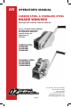
EN OPERATOR’S MANUAL CARBON STEEL & STAINLESS STEEL BRAKE WINCHES Working Loads: 1000 lbs. 1500 lbs. 2000 lbs. Please read the Owner’s Manual carefully before operating the equipment. Keep this manual nearby the equipment at all times. CARBON STEEL: OZ1000BW OZ1500BW OZ2000BW STAINLESS STEEL: OZ1000BWSS OZ1500BWSS OZ2000BWSS P.O. Box 845, Winona, MN 55987 Phone (800) 749-1064 (507) 474-6250 Fax (507) 452-5217 sales@ozliftingproducts.com www.ozliftingproducts.com EN pg.
Table of Contents Pg. 3 . . . . . . . . . . . . . . . . . . . . . . . . . Warranty Pg. 4 . . . . . . . . . . . . . . . . . . . . . . . . . Important Information and Precautions Pg. 5 . . . . . . . . . . . . . . . . . . . . . . . . . Warnings and Precautions Pg. 6 . . . . . . . . . . . . . . . . . . . . . . . . . Installing the Winch Pg. 7 . . . . . . . . . . . . . . . . . . . . . . . . . Installing the Rope Pg. 8 . . . . . . . . . . . . . . . . . . . . . . . . . Concept of Operation / Pre-Operation Pg. 9 .
ONE YEAR WARRANTY OZ Lifting Products LLC® guarantees this product to be free of defects in materials and workmanship for one year from the date of shipment. This warranty does not apply to products that show signs of misuse, overloading, alteration, improper maintenance or negligence. The normal wear and tear of moving parts is excluded from the warranty. Moving parts are defined as brake discs, wire rope and other wear components that are subject to use conditions.
Important Information and Precautions The information in this manual should be used only for the OZ Lifting Brake Winches. This manual contains general instructions dealing with the normal installation, operation, and maintenance of the products described herein. The information provided should not be expected to prepare the user for all possible circumstances. This product should not be installed, operated, or maintained by any person who has not read all the contents of these instructions.
Warnings and Precautions Failure to read and comply with the following warnings may result in a hazardous situation that could lead to death, serious injury, or property damage. Keep this manual near the equipment at all times. Do not remove, alter, or obscure the labels attached to the winch. Contact OZ Lifting Products LLC. for replacement manuals and labels. Do Not operate until all personnel are warned or cleared from the area. Do Not lift people or lift loads over people.
Installing the Winch Choosing a location • Have a qualified professional confirm that the foundation complies with local codes, is rigid and level, and will support the winch under all load conditions. • Avoid areas with corrosives, flammables, combustibles, explosives, and other potentially damaging materials. • Avoid areas defined as hazardous by the National Electric Code, unless proper authorization is received.
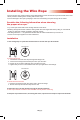
Installing the Wire Rope • Ensure the wire rope spools correctly and is attached firmly to the winch drum to prevent release of the load. • Wear protective clothing when working with the wire rope. • Prevent damage to the rope by keeping it clean and not allowing it to pass through dirt or debris. Consider the following information when choosing the proper wire rope. • Lay of the rope should match the winding direction of the drum.
Concept of Operation 1. Assure that the total force needed to lift the load does not surpass the load rating of the winch. 2. Follow all recommended maintenance and inspections to monitor for any damage that could contribute additional weight to the equipment. 3. A disc brake should be used if loads will be lifted or pulled on an incline. 4. Be aware of variables affecting performance ratings of the equipment. a. Loose spooling and overlapping of the wire rope affects drum capacity.
Inspections In order to maintain quality operation of the product, a regular inspection schedule should be set up by each operator. All inspections should be reported and maintained in a dated record log. These records should be available to all personnel involved with the product, and should be made available to OZ Lifting Products LLC. when a warranty issue is in question. Definitions The following definitions are from the ANSI/ASME B30.21 and will be used in the inspections procedure that follows.
Take note of the following regarding inspections. • Brakes require more than audible and visual inspection. Check daily by operating with and without a load, stopping at various positions to ensure safe operation. If the load coasts or creeps contact the factory for friction disc replacements. • Proper inspection may require disassembly of some parts. Contact the factory before doing so or the applicable warranty may be voided.
Repair of the Winch All repairs must have factory authorization. Contact OZ Lifting LLC. to prevent voiding of the warranty and potential damage to the winch. Perform recommended inspections to identify which parts should be replaced. • Only use OZ Lifting Products LLC. replacement parts. • Contact the local OZ Lifting Products LLC. dealer for replacement parts. Please have the serial number and part number and description available when calling.
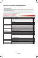
Specifications F E H A D K I M C B J G L Model OZ1000BW - OZ1000BWSS OZ1500BW - OZ1500BWSS OZ2000BW - OZ2000BWSS Safe Working Load (lbs.) 1000 lbs. 1500 lbs. 2000 lbs. Gear Ratio 4.2:1 5:1 10:1 6.22” 7.73” 8.35” 11.10” Dimensions (in.) A B 7.20” 9.36” C 3.46” 4.21” 5.00” D 8.26” 12.68” 12.99” E 1.06” 1.06” 1.06” F 10.43” 10.63” 11.81” G 1.98” 2.30” 2.52” H 4.29” 4.29” 4.29” I 1.90” 2.38” 3.00” J 5.33” 7.00” 7.09” K 10.20” 15.31” 15.35” L 5.
Mounting OZ1000BW OZ1000BWSS OZ1500BW OZ1500BWSS N= 1.73” O= 3.46” P= 1.30” Q= 5.43” R= 0.94” S= 0.79” T= 1.06” U= 1.57” V= 0.41” W= 0.41” x 1.65” X= 0.51” Y= 0.63” N= 2.10” O= 4.20” P= 5.28” Q= 7.56” R= 0.72” S= 1.38” T= 0.79” U= 2.76” V= 0.39” W= 0.39” x 2.17” X= 4.49” Y= 1.14” Z= 1.14” OZ2000BW OZ2000BWSS N= 2.50” O= 5.00” P= 6.36” Q= 9.45” R= 1.94” S= 1.50” T= 1.66” U= 3.00” V= 0.39” W= 0.39” x 1.77” X= 4.70” Y= 0.39”x0.78” Z= 1.15” EN pg.
Parts OZ1000BW - OZ1000BWSS 1. Nut (1) 2. Screw (1) 3. Drum (1) 4. Cover (1) 5. Mounting Base (1) 6. Snap Ring (2) 7. Ratchet Pawl (1) 8. Retaining Ring (1) 9. Bolt (1) 10. Friction Brake (2) 11. Rachet (1) 12. Clip (1) 13. Shaft (1) 14. Cover Part (1) 15. Washer (4) 16. Bolt (2) 17. Bolt (2) 18. Nut (1) 19. Washer (1) 20. Retaining Ring (2) 21. Washer (2) 22. Nut (2) 23. Gear (1) 24. Clip (1) 25. Washer (1) 26. Retaining Ring (1) 27. Handle (1) 28. Washer (1) 29. Nut (1) 40. Wire Rope Cip (1) 11.
Parts OZ2000BW - OZ2000BWSS 1. Nut (1) 2. Screw (1) 3. Drum (1) 4. Cover (1) 5. Nut (1) 6. Munting Base (1) 7. Snap Ring (2) 8. Ratchet Pawl (2) 9. Retaining Ring (2) 10. Bolt (2) 11. Shaft (1) 12. Rataining Ring (1) 13. Washer (1) 14. Gear (1) 15. Gear (1) 16. Shaft (1) 17. Shaft (1) 18. Cover Part (1) 19. Washer (6) 20. Bolt (3) 21. Washer (1) 22. Retaining Ring (1) 23. Handle (1) 24. Washer (1) 25. Nut (1) 26. Nut (1) 27. Washer (1) 28. Bolt (1) 29. Washer (1) 30. Support Pipe (1) 31.
FR GUIDE DE L’OPÉRATEUR ACIER ORDINAIRE ET ACIER INOXYDABLE TREUILS DE FREINAGE Charges de service : 1 000 lb 1 500 lb. 2 000 lb Veuillez lire le manuel de l’utilisateur attentivement avant de faire fonctionner cet équipement. Garder ce manuel à votre portée en tout temps. ACIER ORDINAIRE : OZ1000BW OZ1500BW OZ2000BW ACIER INOXYDABLE : OZ1000BWSS OZ1500BWSS OZ2000BWSS P.O. Box 845, Winona, MN 55987 Téléphone +1 (800) 749-1064 +1 (507) 474-6250 Télécopieur +1 (507) 452-5217 sales@ozliftingproducts.
Table des matières p. 3. . . . . . . . . . . . . . . . . . . . . . . Garantie P. 4. . . . . . . . . . . . . . . . . . . . . . . Renseignements importants et mesures de sécurité P. 5. . . . . . . . . . . . . . . . . . . . . . . Avertissements et mesures de sécurité P. 6. . . . . . . . . . . . . . . . . . . . . . . Installation du treuil P. 7. . . . . . . . . . . . . . . . . . . . . . . Installation du câble P. 8. . . . . . . . . . . . . . . . . . . . . . . Concept de fonctionnement/préfonctionnement P. 9. .
GARANTIE D’UN AN OZ Lifting Products LLC® garantit ce produit contre les défauts de fabrication et de conception pendant un an à compter de la date d’expédition. Cette garantie ne s’applique pas aux produits indiquant qu’il y a eu abus, surcharge, altération, mauvais entretien ou négligence. L’usure normale des pièces en mouvement est exclue de la garantie. Exemples de pièces en mouvement : disques de frein, câbles métalliques et autres composants qui s’usent.
Renseignements importants et mesures de sécurité Les renseignements que contient ce manuel doivent être utilisés pour les treuils à frein OZ Lifting®. Ce manuel contient des instructions générales sur l’installation, le fonctionnement et l’entretien normaux des produits décrits aux présentes. Vous ne devez pas prendre pour acquis que les renseignements fournis préparent l’utilisateur pour toute circonstance possible.
Avertissements et mesures de sécurité Si vous ne lisez pas les avertissements suivants et que vous ne vous y conformez pas, il peut y avoir des situations dangereuses qui pourraient causer la mort, des blessures graves ou des dommages matériels. Garder ce manuel à votre portée en tout temps. Ne pas enlever, ne pas modifier ou ne pas obscurcir les étiquettes attachées au treuil. Contacter OZ Lifting Products LLC® pour des manuels et des étiquettes de rechange.
Installation du treuil Choix d’emplacement • Qu’un professionnel qualifié confirme que la fondation est conforme aux codes locaux, qu’elle est rigide et à niveau et qu’elle supportera le treuil, quelle que soit la charge. • Éviter les endroits corrosifs, inflammables, combustibles, explosifs ou autres qui pourraient causer des dommages. • Éviter les endroits que le code électrique national indique comme étant dangereux à moins qu’une autorisation ait été reçue à cet effet.
Installation du câble métallique • S’assurer que le câble métallique s’enroule correctement et est attaché fermement au tambour du treuil pour éviter qu’il y ait libération de la charge. • Porter des vêtements protecteurs en travaillant avec un câble métallique. • Éviter d’endommager le câble en le gardant propre et en l’empêchant de passer dans de la saleté ou des débris. Prendre en compte les renseignements suivants quand vous choisissez un câble métallique.
Concept de fonctionnement 1. S’assurer que la force totale qu’il faut pour lever la charge ne dépasse pas la capacité de charge du treuil. 2. Respecter toutes les consignes d’entretien et d’inspection pour déterminer tout dommage qui pourrait ajouter du poids à l’équipement. 3. Un frein à disque doit être utilisé si on soulève ou tire des charges sur une inclinaison. 4. Connaître les variables qui affectent les rendements nominaux de l’équipement. a.
Inspection Pour que la qualité de fonctionnement du produit soit bonne, l’opérateur doit faire inspecter le produit régulièrement. Toutes les inspections doivent être consignées et conservées dans un journal. Ces dossiers doivent être accessibles à tout le personnel qui utilise le produit et à OZ Lifting Products LLC® lorsqu’il y a un problème lié à la garantie. Définitions Les définitions suivantes sont tirées de ANSI/ASME B30.21 et doivent être utilisées lors de la procédure d’inspection suivante.
Prendre note de ce qui suit en cas d’inspections régulières. • Les freins requièrent une inspection non seulement audible et visuelle. Les vérifier tous les jours en faisant fonctionner avec et sans charge, vous arrêtant dans diverses positions pour garantir qu’ils fonctionnent bien. Si la charge se déplace, contacter l’usine pour remplacer les disques d’embrayage. • Il se peut que vous deviez désassembler certaines pièces pour les bien inspecter.
Réparation du treuil L’usine doit autoriser toutes les réparations. Contacter OZ Lifting LLC® pour ne pas rendre votre garantie nulle et non avenue et ne pas causer des dommages au treuil. Effectuer les inspections recommandées pour déterminer les pièces à remplacer. • Utiliser seulement des pièces de rechange provenant de OZ Lifting Products LLC®. • Communiquer avec votre concessionnaire OZ Lifting Products LLC® local pour des pièces de rechange.
Spécifications F E H A D K I M C B J G L Modèle OZ1000BW - OZ1000BWSS OZ1500BW - OZ1500BWSS OZ2000BW - OZ2000BWSS Capacité de charge sécuritaire (lb) 1 000 lb 1 500 lb 2 000 lb Rapport de transmission 4.
Montage OZ1000BW OZ1000BWSS OZ1500BW OZ1500BWSS N = 1,73 po O = 3,46 po P = 1,30 po Q = 5,43 po R = 0,94 po S = 0,79 po T = 1,06 po U = 1,57 po V = 0,41 po W = 0,41 po x 1,65 po X = 0,51 po Y = 0,63 po N = 2,10 po O = 4,20 po P = 5,28 po Q = 7,56 po R = 0,72 po S = 1,38 po T = 0,79 po U = 2,76 po V = 0,39 po W = 0,39 po x 2,17 po X = 4,49 po Y = 1,14 po Z = 1,14 po OZ2000BW OZ2000BWSS N = 2,50 po O = 5,00 po P = 6,36 po Q = 9,45 po R = 1,94 po S = 1,50 po T = 1,66 po U = 3,00 po V = 0,39 po W = 0,39 p
Pièces OZ1000BW - OZ1000BWSS 1. Écrou (1) 2. Vis (1) 3. Tambour (1) 4. Couvercle (1) 5. Base de montage (1) 6. Circlip (2) 7. Cliquet à rochet (1) 8. Anneau de retenue (1) 9. Boulon (1) 10. Frein à friction (2) 11. Rochet (1) 12. Pince (1) 13. Arbre (1) 14. Pièce de couvercle (1) 15. Rondelle (4) 16. Boulon (2) 17. Boulon (2) 18. Écrou (1) 19. Rondelle (1) 20. Anneau de retenue (2) 21. Rondelle (2) 22. Écrou (2) 23. Engrenage (1) 24. Pince (1) 25. Rondelle (1) 26. Anneau de retenue (1) 27.
Pièces OZ2000BW - OZ2000BWSS 1. Écrou (1) 2. Vis (1) 3. Tambour (1) 4. Couvercle (1) 5. Écrou (1) 6. Base de montage (1) 7. Circlip (2) 8. Cliquet à rochet (2) 9. Anneau de retenue (2) 10. Boulon (2) 11. Arbre (1) 12. Anneau de retenue (1) 13. Rondelle (1) 14. Engrenage (1) 15. Engrenage (1) 16. Arbre (1) 17. Arbre (1) 18. Pièce de couvercle (1) 19. Rondelle (6) 20. Boulon (3) 21. Rondelle (1) 22. Anneau de retenue (1) 23. Poignée (1) 24. Rondelle (1) 25. Écrou (1) 26. Écrou (1) 27. Rondelle (1) 28.
ES MANUAL DEL OPERADOR ACERO CARBONO Y ACERO INOXIDABLE CABRESTANTE DE FRENO Cargas de trabajo: 1000 lbs. 1500 libras 2000 libras Lea atentamente el Manual del propietario antes de utilizar el equipo. Mantenga este manual cerca del equipo en todo momento. ACERO CARBONO: OZ1000BW OZ1500BW OZ2000BW ACERO INOXIDABLE: OZ1000BWSS OZ1500BWSS OZ2000BWSS P.O. Box 845, Winona, MN 55987 Teléfono (800) 749-1064 (507) 474-6250 Apoyo técnico (507) 457-3346 Fax (507) 452-5217 sales@ozliftingproducts.com www.
Tabla de contenido Pág.3 . . . . . . . . . . . . . . . . . . . . . . . . Garantía Pág.4 . . . . . . . . . . . . . . . . . . . . . . . . Información importante y precauciones Pág.5 . . . . . . . . . . . . . . . . . . . . . . . . Advertencias y precauciones Pág.6 . . . . . . . . . . . . . . . . . . . . . . . . Instalar el cabrestante Pág.7 . . . . . . . . . . . . . . . . . . . . . . . . Instalando la cuerda Pág.8 . . . . . . . . . . . . . . . . . . . . . . . . Concepto de Operación / Preoperación Pág.9 . . .
GARANTÍA DE UN AÑO OZ Lifting Products LLC® garantiza que este producto estará libre de defectos en materiales y mano de obra durante un año a partir de la fecha de envío. Esta garantía no se aplica a productos que muestran signos de mal uso, sobrecarga, alteración, mantenimiento incorrecto o negligencia. El desgaste normal de las piezas móviles está excluido de la garantía. Las partes móviles se definen como discos de freno, cable metálico y otros componentes de desgaste sujetos a condiciones de uso.
Información importante y precauciones La información de este manual debe usarse solo para los cabrestantes de freno OZ. Este manual contiene instrucciones generales que tratan sobre la instalación, operación y mantenimiento normales de los productos descritos aquí. No debe esperarse que la información proporcionada prepare al usuario para todas las circunstancias posibles. Este producto no debe ser instalado, operado o mantenido por ninguna persona que no haya leído todo el contenido de estas instrucciones.
Advertencias y precauciones No leer y cumplir con las siguientes advertencias puede provocar una situación peligrosa que podría provocar la muerte, lesiones graves o daños a la propiedad. Mantenga este manual cerca del equipo en todo momento. No quite, altere ni oculte las etiquetas adheridas al cabrestante. Póngase en contacto con OZ Lifting Products LLC. para reemplazar manuales y etiquetas. No opere hasta que todo el personal esté advertido o despejado del área.
Instalar el cabrestante Elegir una ubicación • Haga que un profesional calificado confirme que la base cumple con los códigos locales, es rígida y nivelada, y soportará el cabrestante en todas las condiciones de carga. • Evite áreas con corrosivos, inflamables, combustibles, explosivos y otros potencialmente materiales dañinos • Evite áreas definidas como peligrosas por el Código Eléctrico Nacional, a menos que se reciba la autorización adecuada.
Instalación del cable • Asegúrese de que el cable metálico se enrolle correctamente y esté firmemente sujeto al tambor del cabrestante para evitar que se libere la carga. • Use ropa protectora cuando trabaje con el cable metálico. • Evite dañar la cuerda manteniéndola limpia y sin permitir que pase a través de suciedad o escombros. Tenga en cuenta la siguiente información al elegir el cable adecuado. • La colocación del cable debe coincidir con la dirección del devanado del tambor.
Concepto de operación 1. A segúrese de que la fuerza total necesaria para levantar la carga no supere la capacidad de carga del cabrestante. 2. Siga todo el mantenimiento recomendado y las inspecciones para controlar cualquier daño que pueda aportar peso adicional al equipo. 3. Se debe usar un freno de disco si las cargas se levantarán o tirarán en una pendiente. 4. Tenga en cuenta las variables que afectan las clasificaciones de rendimiento del equipo. a.
Inspecciones Para mantener la operación de calidad del producto, cada operador debe establecer un programa de inspección regular. Todas las inspecciones deben informarse y mantenerse en un registro de registro fechado. Estos registros deben estar disponibles para todo el personal involucrado con el producto y deben estar disponibles para OZ Lifting Products LLC. cuando un problema de garantía está en duda. Definiciones Las siguientes definiciones son de ANSI / ASME B30.
Tome nota de lo siguiente con respecto a las inspecciones. • Los frenos requieren más que una inspección audible y visual. Verifique diariamente operando con y sin carga, deteniéndose en varias posiciones para garantizar una operación segura. Si la carga se desliza o se arrastra, contacte a la fábrica para reemplazar el disco de fricción. • La inspección adecuada puede requerir el desmontaje de algunas partes. Póngase en contacto con la fábrica antes de hacerlo o la garantía aplicable puede ser anulada.
Reparación del cabrestante Todas las reparaciones deben tener autorización de fábrica. Póngase en contacto con OZ Lifting LLC. para evitar la anulación de la garantía y posibles daños al cabrestante. Realice las inspecciones recomendadas para identificar qué partes deben reemplazarse. • Utilice únicamente OZ Lifting Products LLC. piezas de repuesto. • P óngase en contacto con el local OZ Lifting Products LLC. distribuidor de repuestos.
Especificación F E H A D K I M C B J G L Modelo OZ1000BW - OZ1000BWSS OZ1500BW - OZ1500BWSS OZ2000BW - OZ2000BWSS Carga de trabajo segura (lb) 1000 lbs. 1500 lbs. 2000 lbs. Relación de transmisión 4.2:1 5:1 10:1 6.22” 7.73” 8.35” 11.10” Dimensiones (in) A B 7.20” 9.36” C 3.46” 4.21” 5.00” D 8.26” 12.68” 12.99” E 1.06” 1.06” 1.06” F 10.43” 10.63” 11.81” G 1.98” 2.30” 2.52” H 4.29” 4.29” 4.29” I 1.90” 2.38” 3.00” J 5.33” 7.00” 7.09” K 10.20” 15.
Montaje OZ1000BW OZ1000BWSS OZ1500BW OZ1500BWSS N= 1.73” O= 3.46” P= 1.30” Q= 5.43” R= 0.94” S= 0.79” T= 1.06” U= 1.57” V= 0.41” W= 0.41” x 1.65” X= 0.51” Y= 0.63” N= 2.10” O= 4.20” P= 5.28” Q= 7.56” R= 0.72” S= 1.38” T= 0.79” U= 2.76” V= 0.39” W= 0.39” x 2.17” X= 4.49” Y= 1.14” Z= 1.14” OZ2000BW OZ2000BWSS N= 2.50” O= 5.00” P= 6.36” Q= 9.45” R= 1.94” S= 1.50” T= 1.66” U= 3.00” V= 0.39” W= 0.39” x 1.77” X= 4.70” Y= 0.39”x0.78” Z= 1.15” ES pg.
Partes OZ1000BW - OZ1000BWSS 1. Tuerca (1) 2. Tornillo (1) 3. Tambor (1) 4. Cubierta (1) 5. Base de montaje (1) 6. Anillo de retención (2) 7. Trinquete (1) 8. Anillo de retención (1) 9. Perno (1) 10. Freno de fricción (2) 11. Trinquete (1) 12. Clip (1) 13. Eje (1) 14. Cubierta (1) 15. Arandela (4) 16. Perno (2) 17. Perno (2) 18. Tuerca (1) 19. Arandela (1) 20. Anillo de retención (2) 21. Arandela (2) 22. Tuerca (2) 23. Engranaje (1) 24. Clip (1) 25. Arandela (1) 26. Anillo de retención (1) 27.
Partes OZ2000BW - OZ2000BWSS 1. Tuerca (1) 2. Tornillo (1) 3. Tambor (1) 4. Cubierta (1) 5. Tuerca (1) 6. Base de montaje (1) 7. Anillo de retención (2) 8. Trinquete (2) 9. Anillo de retención (2) 10. Perno (2) 11. Eje (1) 12. Anillo de retención (1) 13. Arandela (1) 14. Engranaje (1) 15. Engranaje (1) 16. Eje (1) 17. Eje (1) 18. Cubierta (1) 19. Arandela (6) 20. Perno (3) 21. Arandela (1) 22. Anillo de retención (1) 23. Manija (1) 24. Arandela (1) 25. Tuerca (1) 26. Tuerca (1) 27. Arandela (1) 28.
P.O. Box 845, Winona, MN 55987 Phone (800) 749-1064 (507) 474-6250 Fax (507) 452-5217 sales@ozliftingproducts.com www.ozliftingproducts.com Rev.