ULTRA EDGE SEQUENTIAL SERVO ROLL FEED 6/3/2002 TABLE OF CONTENTS DESCRIPTION PAGE 1 INSTALLATION ............................................................................................................................................ 3 1.1 MECHANICAL INSTALLATION ......................................................................................................... 3 1.2 ELECTRICAL INSTALLATION...........................................................................................................
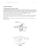
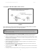
ULTRA EDGE SEQUENTIAL SERVO ROLL FEED 6/3/2002 1 INSTALLATION 1.1 MECHANICAL INSTALLATION The Ultra Edge Sequential Servo Roll Feed is supplied with an adjustable mounting bracket. The feed should be securely mounted to the press frame. (A transition bracket is sometimes required in certain applications.) The feed should be centered, square, and perpendicular to the pass line of the press. It should be mounted at a height that will accommodate the appropriate die sets.
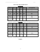
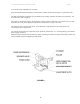
ULTRA EDGE SEQUENTIAL SERVO ROLL FEED 6/3/2002 MOUNTING HOLE DIMENSIONS ENGLISH-INCHES DIMENSION A SRF-100 SRF-125 SRF-200 SRF-300 SRF- 400 / 500 / 600 1.18 1.97 1.97 1.97 1.97 B 1.97 3.15 3.94 3.94 3.94 C 3.94 6.30 7.87 7.87 7.87 D - - - TAP M14 M16 M16 M16 M16 E MIN. 2.2 2.4 2.4 2.4 2.4 PASS LINE ADJUSTMENT +2 -0.0 +2.4 +2.4 +2.4 +2.4 WIDTH OF 9.72 12.13 14.88 18.82 22.76 / 26.69 / 30.63 MTG. PLATE -0.0 5.91 -0.0 -0.0 -0.
ULTRA EDGE SEQUENTIAL SERVO ROLL FEED 6/3/2002 1.2 ELECTRICAL INSTALLATION The Ultra Edge Sequential Servo Roll Feed has been designed to make electrical connections quickly and easily. All that is required is a "clean" 110 VAC (220 VAC for CE models) single-phase 15-ampere source that must be connected to the corresponding terminal blocks (main disconnect switch – for CE models). It is recommended that #12 MTW (Machine Tool Wire) be used for the primary power supply input.
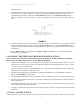
ULTRA EDGE SEQUENTIAL SERVO ROLL FEED 6/3/2002 1.3 LOADING THE FEED (PRESS APPLICATION) FIGURE 3 Prior to this step, the electrical control must be powered up and all needed parameters are loaded. (Refer to the Ultra Edge Sequential Servo Feed Operating Manual.) NOTE: This example is based on using PLS (Programmable Limit Switch), but all PLS timing notes can be easily translated to other forms of timing. 1. Put the Ultra Edge Sequential control into “MANUAL MODE”.
ULTRA EDGE SEQUENTIAL SERVO ROLL FEED 6/3/2002 the feed working. 8. Jog the press down slowly observing when the longest pilot would engage the pilot hole in the material if the material were there. (Refer to Figure 4.) Note the press positional readout and put this setting into your Programmable Limit Switch (PLS) for the ‘Pilot Release On’ setting. The ‘Pilot Release Off’ setting, in most cases, should be 180º. (See Figure 5.) Some drawing applications require the rolls to remain open past 180º.
ULTRA EDGE SEQUENTIAL SERVO ROLL FEED 6/3/2002 it up by the blade. In this case the wiring must be considered very carefully. The backing up the material in a Press application requires: - A cutter bottom position sensor to be wired to the control. The backing up the material in a Punching Bench application requires: - A cutter bottom position sensor to be wired to the control: - A cutter top position sensor to be wired to the control.
ULTRA EDGE SEQUENTIAL SERVO ROLL FEED 6/3/2002 NOTES ABOUT ‘POSSIBLE PROBLEM TOOLING’: * o A tight die, one that is not square, or has other tooling problems, will cause significant difficulty and downtime. Accuracy in feeding is directly related to how easily the feeder can position the strip in the die. Binding, bad part ejection, or sticking parts may cause the material to "jam" in the die.
ULTRA EDGE SEQUENTIAL SERVO ROLL FEED 6/3/2002 (Use a shim on top of the material, if needed.) Position the Pilot Release mechanism so that with the cylinder piston fully extended, it is against the roller. The SRF Pilot Release mechanism is pre-assembled, only needing outside air and electrical connections. For air connections, refer to Figure 6. The release is operated by applying the appropriate voltage signal to actuate the 3-way solenoid valve to open the feeder rolls.
ULTRA EDGE SEQUENTIAL SERVO ROLL FEED 6/3/2002 3 MAINTENANCE The Ultra Edge Sequential Servo Roll Feed needs very little maintenance to keep the system operating at its optimum performance. o This precision equipment must be kept as clean as possible. This is especially important if large amounts of air suspended oil mists in combination with “dirty metals” are used. The resulting abrasive dust can attach itself to the feed rolls and other surfaces, leading to premature wear on many parts.
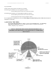
ULTRA EDGE SEQUENTIAL SERVO ROLL FEED 6/3/2002 4 ROLL FEED PARTS LIST FIGURE 7 12
ULTRA EDGE SEQUENTIAL SERVO ROLL FEED 6/3/2002 ITEM QTY DESCRIPTION 1 1 BEARING HOUSING - LEFT SIDE PLATE 2 1 BEARING HOUSING - RIGHT SIDE PLATE 3 1 PLATE- CASCADE MTG. 4 1 PLATE - FEED MTG.
ULTRA EDGE SEQUENTIAL SERVO ROLL FEED 6/3/2002 41 2 BAR - GUIDE ROLLER 42 2 CLAMP - GUIDE BAR 43 2 GUIDE ROLLER 44 4 SPACER - GUIDE ROLLER 45 2 NUT - T SLOT 46 3 ROLL - CASCADE, ENTRY 47 3 SHAFT - ROLL 48 10 BEARING - GUIDE & ENTRY ROLL 49 1 TRANSITION PLATE 50 1 ADJUSTMENT TAB 51 1 SCREW - HEX HD 52 1 NUT - HEX, JAM 53 1 KEY 22 mm x 5 mm x 110 mm 54 2 KEY 22 mm x 12 mm x 40 mm 55 1 STRIKER - RELEASE ACTUATOR 56 1 ARM - ADJUST 57 1 ARM - FIXED 58 1 BLOC
WARNING This equipment offers various means of operating or controlling machines. The operator must not be in or near the point-ofoperation of the machine, or the operating parts of any equipment installed on the machine, or bodily injury could result. The EMPLOYER must post adequate warning signs onto the machine with proper warnings for his machine and the specific application to which the machine and equipment are being applied. Occupational Safety and Health Act (OSHA) Sections 1910.211, 1910.