
Specification Sheet


© 2021 AAMP Global. All rights reserved. PAC is a Power Brand of AAMP Global.
PAC-audio.com
Pacific Accessory Corporation
Page 2
Rev: 2
Date:020922
Advanced Amplier Interface
for Select Ford Vehicles
AP4-FD31
Installation
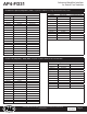
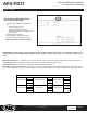
1. Access the factory amplier (Audio Digital Sound Processing Module). Amplier locations are listed starting on
Page 3.
2. Disconnect the 20-pin, 8-pin and A2B USB connectors from the amplier. The amplier can be removed or left in
the vehicle.
3. Plug the 20-pin, 8-pin and A2B USB cables into the matching connectors on the AmpPRO (AP4FD31HAR)
harness.
4. Before connecting the interface, set any feature DIP switches that apply to the install:
a. DIP switch 1 is used for two channel mode. In this mode, all outputs will be non-fading and all chimes are diverted
through channels 1 & 2 and TOSLINK.
b. Set DIP switch 2 on (down) to lower the RCA output voltage to 4v. Leave DIP switch 2 o (up) to keep the RCA
output voltage at 5v. See troubleshooting section on Page 11 for more details.
c. DIP switch 3 is not used and should remain o (up).
d. Set DIP switch 4 to on (down) position if installing interface in a Mach-E. For all other vehicle models, DIP switch
4 should be o (up).
5. Connect the AmpPRO harness to the AmpPRO Interface Connector 1.
6. Connect the level control knob cable to the interface.
7. Connect the signal cables (RCA/TOSLINK) and remote input from the aftermarket amplier.
NOTE! The aftermarket amplier must have a very solid ground and the amplier power/ground
connections should be made before connecting the RCA's or Remote Turn On to the AP4-FD31!
On aluminum framed vehicles, it is recommended to ground directly to the battery.
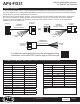
Wiring Connection Chart
Front
1/L
2/R
4/R
5 6
3/L
Remote Amp Turn On +
2A Max Output
Rear
Sub
TOSLINK
20-pin
Amplifier
8-pin
Amplifier
A²B USB
Amplifier
To Vehicle Amplifier Harness
Speaker
Leads
1-10
Non-Fading
Level Control
Knob
To Aftermarket
Amplifier
AP4FD31HAR