
Instruction Manual


RP5-GM51
Radio Replacement & Steering Wheel Control Interface
with OnStar Retention for General Motors Vehicles
Pacic Accessory Corporation
®
| Santa Ana, California 92705 | Ph. 866-931-8021 | support@pac-audio.com
©2014 Pacic Accessory Corporation
www.pac-audio.com
Pacific Accessory Corporation
Rev. 090914
Page 2
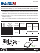
1.The radio select rotary switch on the side of the interface must be adjusted to the proper radio
setting before plugging the interface into the vehicle.
2. Make all connections as described in the chart on page 1.
3. Plug the CMX chime module in if necessary. PLEASE NOTE: In order to get the best possible sound out of the CMX please mount it in a place
free and clear of any obstructions, preferably as close as possible to the bottom of the dash pointing down toward the oor of the vehicle.
4. The Mute loop (if not cut) will turn the accessory output off when an OnStar is activated. If the aftermarket radio has a mute input cut this loop
and connect the inside brown wire (next to the blue/white wire) to the mute input.
5. Connect the SWC wire according to the chart on page 1 (aftermarket radio MUST support a wired remote input).
6. If you wish to reassign functions to the SWC follow the programming instructions on the next page.
7. If the vehicle has a factory amplier (Bose) the speaker wires of the interface will need to be extended and run to behind the rear seat and
connected to the factory amplier output wires. The amplier is located at the bottom center of the rear wall of the vehicles cabin. (See below
for the factory wire colors that will be found at the amplier)
1
2
3
4
5
6
7
8
9
0
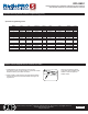
Alpine JVC Kenwood Clarion Pioneer/Other Sony Fusion
1 2 3 4 7 8 9
Other = Advent, BOYO, Dual, Lightning Audio, Visteon,
SET RADIO SELECT SWITCH
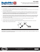
a. If you wish to retain the steering wheel control buttons you must hardwire them into the RP5-GM51. The
wire you need to connect into can be found by removing the plastic panel located beneath the steering
wheel column and accessing the bundle of wires which houses the Green/Black wire (Fig. 1). Once you
have located the Green/Black wire in the vehicle you must connect the Green/Black wire coming from
the vehicle side connections of the interface to this wire. This is a data signal so to ensure consistent
operation please solder the wires together. DO NOT cut this wire in half.
b. If you wish to retain the factory reverse camera you must solder an RCA end onto the signal wires.
The wires you will need can be found at the Human Machine Interface Control Module (HMICM). This
module is located behind the lower glove box and can be accessed by removing the 4 - T15 bolts
securing the lower glove box to the dash. Once you have located the HMICM in the vehicle, locate the
12 pin connector on the far left (Fig 2.). If the vehicle has the base radio (RPO code IO3) the wires will
be in the 8 pin connector located at the radio brain. The wires you will need are located in pins 5 and 6
in either connector. Pin 5- Grey/Yellow - Camera Positive, Pin 6 - White/blue - Camera Negative.
Fig. 1
Fig. 2
Installation Steps
Pin # Wire Color Description
1 Dk. Blue / Grey Subwoofer +
2 Yellow Right Front Spk +
3 Dk. Blue Left Front Spk +
4 Red / Yellow Constant +12V
5 Grey / Black Subwoofer -
6 Yellow / Black Right Front Spk -
7 Brown / Dk. Blue Left Front Spk -
8 Black Ground
Pin # Wire Color Description
4 Brown / Lt. Green Right Front Tweeter + (UQA Only)
5 Yellow / Dk. Blue Left Front Tweeter + (UQA Only)
6 White Right Rear Spk +
7 Lt. Green Left Rear Spk +
12 Purple / Brown Right Front Tweeter - (UQA Only)
13 Yellow / Grey Left Front Tweeter - (UQA Only)
14 Dk. Blue / Black Right Rear Spk -
15 Lt. Green / Black Left Rear Spk -