
User's Manual


English
Installation
1. Ensure your product comes with the items indicated on page 4; if not please contact
your dealer.
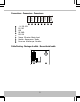
2. Mount reader within panel so that the front cover fits through the aperture and clamp
using nuts suitable for the studs.
3. Connect cable to circuit board — see page 5.
4. Set output format — see page 6.
5. Configure reader — see page 7.
6. Apply power when all readers are installed.
Notes
•
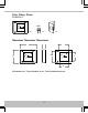
The reader is designed to fit within a standard reader panel. Holes on the reader
accept M3 (metric) / #4 (UTS) posts.
•
Mount readers >3′ / 1m apart, e.g. on either side of the door. Mounting on metal
surfaces will reduce the reading range.
•
If the reader is being used to enter credential information to arm a system, the
reader must be located within 3′ / 1m of the panel’s main keypad or display.
•
For outside readers, use corrosion-resistant fixings and apply silicone sealant to
the backplate before fixing to the wall.
•
The supplied MOV (Metal Oxide Varistor, Anglia Components P/N B72207S250K101)
should be fitted across the power terminals of the lock to suppress back EMF. Any
suppression diodes fitted in the lock / lock circuit must be removed.
•
Output format and reader configuration can be changed without disconnecting the
power supply. The reader automatically restarts with the new configuration.
8
English