
User Manual


Central Network Controller Installation Guide 15162 Ver 2.8 DRAFT E
© 2002 Blick USA, Inc. Page 9
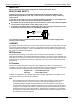
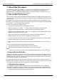
+-BATTERY
12V
3A 3A
BATTERY
NETWORK
CONTROLLER
MAINS I/P
T250mA
RL1 RL3 RL4RL2
Ext Int
Figure 4 Power Supply Unit - Rear View
2.1.1 LED Operation
The two LEDs provided on the CNC indicate the current status of the mains and battery supply. The
following table indicates the status of each LED under different conditions.
Power
Red LED (
)
Green LED (
)
Mains, with battery ON ON
Mains, with no battery ON ON
No mains, with battery OFF ON
No mains, battery low (<10.5V) OFF OFF
No mains, no battery OFF OFF
Note
The battery can be low (<10.5V) but it will still operate the CNC as there has been some leeway
allowed between the battery low indication and the CNC failing. This allows sufficient time for the
battery to be changed.
2.2 Internal Features
You should not need to remove the lid of the CNC unless upgrading the software. The electronics are
contained on a single circuit board.
Figure 5 CNC - Internal Components