
User Manual


15263 Ver 2.1 DRAFT E PAC Portico 2200/1200 Series Installation Guide
Page 6 © 2003 Blick USA, Inc.
10.3 Dial Back Transactions....................................................................................................77
10.4 'Forget' Transactions .......................................................................................................78
11. Specifications ......................................................................................................................79
11.1 Environmental..................................................................................................................79
11.2 Power Supply .................................................................................................................. 79
11.3 Cable ............................................................................................................................... 79
11.4 Mean Time Between Failures.......................................................................................... 79
12. Index .....................................................................................................................................81
Table of Figures
Figure 1 Typical Components of an Access Control System 10
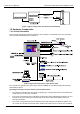
Figure 2 Typical Connections for a PAC Portico 2200 10
Figure 3 Possible Reader Locations for Local Anti-Passback 17
Figure 4 System Diagram - Front Panel Administration 21
Figure 5 PC Interface Kit System 22
Figure 6 Single Site CNC System 23
Figure 7 Multi-Site CNC System 24
Figure 8 Six Wire Bus Configuration 25
Figure 9 Six Wire Bus Wiring 26
Figure 10 Line Driver Wiring Diagram 28
Figure 11 Door Controller with Front Panel 30
Figure 12 Door Controller without Front Panel 31
Figure 13 PAC Portico 2200IP/1200IP Door Controller with Cover 32
Figure 14 Recommended Wiring Layout 33
Figure 15 Metal Enclosure Option 1 34
Figure 16 Metal Enclosure Option 2 35
Figure 17 Rear View of Door Controller Baseplate 36
Figure 18 Using an External Battery Charger 40
Figure 19 Reader with Request to Exit and Door Monitoring 43
Figure 20 In/Out Readers Without Arming/Disarming 44
Figure 21 In/Out Readers With Manual Arming/Disarming 45
Figure 22 In/Out With Automatic Arming/Disarming 45
Figure 23 Emergency Override / Free Exit Wiring 46
Figure 24 Lock Output Wiring 47
Figure 25 Wiegand Connections 49
Figure 26 Relay Outputs 50
Figure 27 Enclosure Tamper Wiring 51
Figure 28 Override Input Wiring 51
Figure 29 Option Switch Settings 54