
Installation Manual

2
Pacic Accessory Corporation
Santa Ana, CA 92705
techsupport@pac-audio.com • www.pac-audio.com
Copyright 2014 Pacic Accessory Corporation. Content subject to change without notice.
Gain Level Adjustment
New School – *Adjust with remote level at full.
Required items: Digital Multi-Meter, Test track media @ 1kHz and 100Hz. Max Amplier Line-level Input Voltage Specication
(i.e., 4vrms, 8vrms,
etc. refer to amplier specications documentation)
Proper level adjustment is crucial for obtaining the best possible sound quality. Following the guidelines below will enable you to properly set the
output gain of the LP7-2RR using equipment that is readily available. Although this device can be set by ear (Old School), we recommend using a
multi-meter and test tracks for pinpoint accuracy and the least chance of noise.
Ampliers usually have 2, 4 or 8v max line-level input ratings but this can vary. This max line-level input will be your target setting you will read on
the multi-meter. Perform the following procedure for each amplier you are installing.
Old School – *Adjust with remote level at full.
1. Start with gain adjustment levels on LP7-2R and ampliers set to minimum.
2. Turn source unit to ¾ maximum volume and play a familiar song that has dynamic attributes.
For example, if your volume goes to 40 you will turn it up to 30 and play a song that has some
quiet sections and some really loud sections.
3. Slowly adjust front channel gain of LP7-2R until just a hint of distortion is audible, and then
back down gain just under that threshold and the distortion goes away. (gure 2)
Figure 2
Example:
Amplier 1 (Mid/High frequency) has a maximum 4v input voltage, so you will be targeting a 4
volt output voltage from the LP7-2R.
or
Amplier 1 (Sub frequency) has a maximum 2v input voltage, so you will be targeting a 2 volt
output voltage from the LP7-2R.
1. Start with gain adjustment levels on LP7-2R and ampliers set to minimum.
2. Turn source unit to ¾ maximum volume and start test track
(1kHz for mid/high or full range, 100Hz for sub).
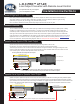
3. Choose either left or right channel - With multi-meter, test output of LP7-2R .
Probe with negative on RCA shield and positive in center of RCA output. (gure 1)
4. Slowly adjust level on LP7-2R until you reach the target voltage of the amplier. (gure 2)
5. Turn volume down and system off.
6. Connect RCAs, set gains on ampliers to minimum
7. Turn system on and ne tune gains of amplier (if needed).
Figure 1
Set meter to AC voltage.
Connect Red probe to Voltage (V)
Black to Common (COM)
_
+
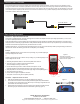
Remote Level Controller
Find a suitable location for the remote level controller and mount it with screws, wireties or doubletape. If custom mounting is more desirable, the outer
housing is removable and the circuit board is perforated so it can be cut away. Use this option for mounting in tight locations and behind factory knockouts.
Connect the remote to the LP7-2R harness via th included 3.5mm to 3.5mm extension cable. If a longer cable is needed, any standard stereo 3.5mm cable
can be utilized. Adjust the amplier gain with the level on the remote level controller all the way up, after the amplier gain have been adjusted you can then
use the level controller to attenuate the output from full.
To LP7-2R Harness