
Product Manual


A scraping noise indicates improper clear
ances, requiring disassembly and reshim-
mimg.
12. With pump running and with pump body
full of water, put a vacuum gauge over the
suction opening and check suction ability
according to section IV.
4
A. DISASSEMBLY
1. Remove the ten 1/4”-20 body screws. Re-
move the pump body.
2. Remove the rubber check valve from the
volute and the large O-ring from around the
perimeter of the bracket.
3. Remove the volute.
4. Unscrew the impeller screw and remove
it along with the small O-ring. Slide the
impeller and the key off the shaft. (to
facilitate removal of the impeller, gently
force two screw drivers 180 degrees apart,
under the back of the impeller and gently
pry the impeller off the shaft.)
5. One half of the shaft seal is in the impel-
ler hub, and the other half is around the
shaft, inside the bracket. The impeller
portion of the seal can be carefully pried
out with a screwdriver. If you plan to reuse
the seal, be careful not to nick or scratch
either of it’s at polished surfaces.
6. Remove the four bracket screws* and the
small O-rings on each screw and remove
the 9” O-ring segment which forms an arc
over the shaft seal. Pull the bracket off the
engine. The stationary half of the shaft seal
can now be pressed out from the back
side the bracket. Use a round wooden plug
1-3/16 in diameter and carefully press the
seal out straight if it might be reused. (Be
careful not to damage the seal face).
Remove the O-ring from around the seal.
*NOTE: If plugs are installed over the
bracket screws on your pump remove the
plugs by screwing a body screw into the
hole and carefully pulling them out.
B. ASSEMBLY
1. Put all parts back together in the reverse of
the order used in disassembly.
2. When installing a new seal, always replace
both elements of the seal and put the
O-ring in place around the bracket half of
the seal. Protect the smooth lapped
sealing surfaces from damage when
pressing in the new parts. To press the
bracket portion of the seal in place, use
a piece of pipe that will bear only on the
ange of the metal seal case. Be sure both
seal halves are fully seated and square
with respect to the pump shaft.
3. During the nal assembly, it is recommend-
ed that all of the screw head O-ring seals
(item #8, g. 7) be replaced. Lubricate
these with vegetable oil (DO NOT use
petroleum base oil) before assembly.
4. Use a thread locking compound such as
Loctite #242 on the bracket screws (Item
#9 in g. 7), and on the impeller screw (Item
#16 in g. 7).
5. The clearance between the impeller vanes
and the volute face should be about .015”
to .025” for good performance. This front
clearance can be attained by shimming. The
impeller can be shimmed from the bracket
face by:
a. Adding one or more washer type shims
(Item #30 g. 7) under the impeller hub.
The impeller can be shimmed closer to
the bracket by:
a. Removing one or more washer type
shims (Item #30 g. 7) from under the
impeller hub (if any were used on your
pump).
After shimming turn the impeller to ensure
that the impeller is not touching the bracket.
If necessary, add or remove more shims.
Be sure that the impeller is completely on
the shaft when checking shimming. Put
pressure only on the hub when pressing
impeller on the shaft.
6. Check the impeller vanes for proper height.
The following measurements should be
found when measuring the vane height on
the outside perimeter of the impeller:
*Impeller Number Vane height at tip of vane
58-0667 .535”
58-0704 .535”
58-0706 .535”
58-0974 .600”
58-0975 .975”
*See parts list for further description
NOTE: If the vane thicknesses are less
than noted above, shimming up to .090”
(Item #30 g. 7) is acceptable. If more
shimming than .090” is required, the
impeller should be replaced.
7. Check volute face for excessive wear. Slight
scoring is acceptable.
8. The four bracket screws (with O-ring on
each) holding pump bracket to engine
should be tightened securely with a large
screwdriver or socket wrench.
9. NOTE: Carefully assemble the pump. The
bracket and the pump body when
assembled will hold the volute in place.
10. Lubricate the body O-ring with a
vegetable based lubricant before replacing it
in the pump.
11. When assembling nipples, ttings and
elbows into the pump body, wrap the male
threads with teon sealing tape. Proper
tightness is hand tight plus one full turn with
a pipe wrench.
CAUTION: After pump is assembled and
before starting, rotate the shaft by hand and
listen for possible scraping noises.
V. PUMP DISASSEMBLY AND REPAIR
VI. SPECIAL INFORMATION
A. FLEXIBLE COUPLED PUMPS:
COUPLING ALIGNMENT
Measure the diameter of the pump shaft
and power unit shaft. Choose the
appropriate coupling for your pump and
power unit. (See exible couplings chart
VI-A). Proper shaft and coupling alignment
reduces vibration and prevents premature
coupling failure. The following 8 steps help
in obtaining proper shaft alignment:
1. Make sure you use a rigid base plate
large enough for the assembly of the pump
and the drive unit. We offer kits, 58-0028
and 58-0016, for this purpose. (See base
plate kits listed after couplings chart VI-A)**
2. Place the pump and drive unit on the
baseplate.
3. Measure the distance between the
centerline of the of the pump shaft
and the baseplate surface.
4. Measure the distance between the cen-
terline of the drive unit shaft and the
baseplate.
5. Compare measurements obtained from
steps 3 and 4 and use spacer blocks for
height adjustment to ensure alignment of
both shafts.
6. Place the coupling halves over each
shaft. Put the “spider” between the two
halves and couple the two halves
together.
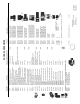
7. To assure parallel alignment (Figure 5)
place a straight edge along the side of
INCORRECT
CORRECT
PUMP SHAFT
PUMP SHAFT DRIVE SHAFT
DRIVE SHAFT
COUPLING
COUPLING
FIGURE 5
both coupling halves in two different locations,
90 degrees apart. The coupling is aligned
when the straight edge rests squarely in the
sides of both coupling halves.
8. To avoid angular misalignment, insert a
measuring device (taper gauge or feeler gauge)
between the coupling faces at four locations 90
degrees apart. (See arrows in Figure 6) and
measure the gap at each of the four locations.
For proper alignment all four measurements
should be equal. Reshimming may be
required to achieve this alignment.
90
O
ANGLE
DRIVE
SHAFT
FEELER
GAUGE
FIGURE 6
COUPLING
PART
NUMBER
POWER
UNIT SHAFT*
DIAMETER
ELECTRIC
MOTOR
FRAME SIZES
58-0786 .652” 56
58-0786 .875” 143T-145T
182-184
58-0787 1.125” 183T-184T
213T-215T
58-0788 1.375” 213-215
58-0875 1” -------
58-0876 .75” -------
FLEXIBLE COUPLING CHART VI-A
* One half of each coupling has a .750” diameter
bore to t the pedestal pump shaft.