Packard Bell EasyNote B3 Disassembly Manual
1 Table of Contents Overview....................................................................................................................................................... 2 Technician Notes.......................................................................................................................................... 2 Disassembly Instructions..............................................................................................................................
2 Overview This document contains step-by-step disassembly instructions for the EasyNote B3 chassis. The instructions are illustrated where necessary with images of the part that is being removed or disassembled. Furthermore, the screws that are removed are shown next to the image of the parts themselves. Packard Bell reserves the right to make changes to the EasyNote B3 chassis without notice. Technician Notes Only technicians authorized by NEC Computers International B.V.
3 Hazardous Voltage There is hazardous voltage present inside the computer when it is connected to an AC supply, even when the computer’ s power switch is off. Exposure to hazardous voltage could cause personal injury. To avoid risk of injury, contact an Authorized Service Provider for proper (un)installation of optional hardware devices. Avoid Electrostatic Discharge Electrostatic electricity can easily damage circuit cards and integrated circuits (ICs).
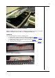
4 System Disassembly HDD To remove the HDD, perform the following steps: 1. 2. 3. 4. Remove the HDD cover (2 screws marked A on Picture 1). Remove the 2 screws holding the HDD bracket. Pull back the HDD bracket and gently lift out the HDD. Remove the bracket from the HDD (4 screws). Picture 1. Bottom Base Memory Module To remove a memory module, perform the following steps: 1. Remove the bottom cover (5 screws marked B on Picture 1). 2. Push the metal clips holding the SO-DIMM aside. 3.
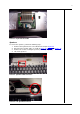
5 Picture 2. Power Cable of Heat Sink Assembly Picture 3. Heat Sink Assembly Screws WiFi LAN Adapter (Mini PCI) To remove the Wireless LAN Adapter (mini PCI), perform the following steps: 1. 2. 3. 4. Remove the bottom cover (5 screws marked B on Picture 1). Push the clips securing the card sideways; the card will ‘ eject’ . Disconnect the WLAN antenna (see Picture 4). Lift out the mini PCI card.
6 Picture 4. WLAN Mini PCI Adapter and Antenna Note: The WLAN card has 2 connectors: MAIN and AUX. Please be sure to connect the antenna to the MAIN connector when re-assembling the WLAN card! Keyboard To remove the keyboard, perform the following steps: 1. 2. 3. 4. 5. Remove the 3 screws located in the battery compartment (Picture 5). Push up the keyboard cover in the area indicated with the 2 arrows in Picture 5. Remove the 3 screws securing the keyboard shown in Picture 6.
7 Picture 7. Keyboard Flat Cable Speakers To remove the speakers, perform the following steps: 1. 2. 3. 4. Remove the keyboard cover as described in the chapter Keyboard. Disconnect the speaker cables as shown in Picture 8, Picture 9, and Picture 10. Remove the screws securing the speaker (2 screws per speaker). Lift out the speakers. Picture 8. Speaker Cable Connector Picture 9.
8 Picture 10. Right Speaker Connector LCD Screen Assembly To remove the LCD screen assembly, perform the following steps: 1. Remove the keyboard top cover as described in the chapter Keyboard. 2. Remove the LCD hinge covers; these are ‘ clicked’in place on the backside of the notebook. The best way is to leverage them slightly using a flat-head screwdriver. 3. Disconnect the LCD cables. 4. Disconnect the WLAN antenna.
9 Picture 11. Bottom Base Screws Picture 12. Glide Pad Flat Cable Picture 13.
10 Picture 14. Main Board Screws Translation Board The translation board is a small PCB with a USB, VGA-Out and AC adapter connector. To remove it, perform the following steps: 1. Perform all steps to remove the main board (see chapter Main Board). 2. Remove the screw holding the translation board. 3. Lift out the translation board. Modem To remove the modem, perform the following steps: 1. 2. 3. 4. 5. Perform all steps to remove the main board (see chapter Main Board).
11 Picture 15. LCD Switch LCD Screen Disassembly LCD Lid Assembly To remove the LCD lid assembly, perform the following steps: 1. Remove the keyboard top cover as described above. 2. Remove the LCD hinge covers; these are ‘ clicked’in place on the backside of the notebook. The easiest way is to leverage them slightly using a flat-head screwdriver. 3. Disconnect the LCD cables. 4. Disconnect the WLAN antenna.
12 Picture 16. LCD Bezel Inverter Board To remove the inverter board, perform the following steps: 1. Unplug the cable on the inverter board. 2. Remove the screw (screw A in Picture 17). 3. Take away the inverter board. Picture 17. LCD Assembly Without Bezel LCD Panel To remove the LCD panel, perform the following steps: 1. Remove the 4 screws holding the hinges (marked B in Picture 17). 2.
13 3. Gently lift out the LCD panel. 4. Remove the remaining 2 screws on each side of the LCD panel to remove the brackets. Wireless Antenna To remove the wireless antenna, perform the following steps: 1. After removing the LCD panel, remove the tape holding the antenna. 2. Remove the screw (see Picture 18). Picture 18. Wireless Antenna Screw LCD Lid Hook To remove the LCD lid hook, perform the following steps: 1. After removing the LCD panel, you can take out the hook.
14 Notice The information in this guide is subject to change without notice. This guide contains information protected by copyright. No part of this guide may be photocopied or reproduced in any form or by any means without prior written consent from NEC Computers International B.V. NEC COMPUTERS INTERNATIONAL B.V.