Chapter 3 113
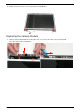
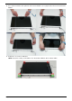
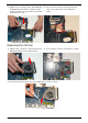
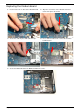
2. Press down around the entire perimeter of the bezel until there are no gaps between the bezel and the LCD
Module.
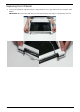
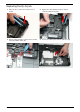
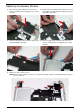
3. Replace the six screws as indicated.
NOTE: The Bezel securing screws differ in size: Red callout—M2.5*5, Green callout—M2*4.